Zero-clearance arc swing mechanism based on machine tool and implementation method thereof

A swing mechanism, no gap technology, applied in mechanical equipment, transmission, belt/chain/gear, etc., can solve the problems of insufficient driving rigidity, increased backlash, gap, etc., and achieve the effect of overcoming defects and eliminating gaps

Active Publication Date: 2016-01-27
成都煜鼎特种加工技术有限公司
View PDF6 Cites 7 Cited by
  • Summary
  • Abstract
  • Description
  • Claims
  • Application Information

AI Technical Summary

Problems solved by technology

[0002] In the prior art, in the field of machine tool processing technology, as long as it is a mechanism that performs an oscillating movement within ±45°, it uses a worm gear pair transmission or a gear pair transmission to realize the swing, which mainly has the following defects: (1) There is an assembly Transmission clearance; (2) After long-term use, it is inevitable that there will be a clearance due to sliding wear on the tooth surface, resulting in an increase in the backlash of the reciprocating swing and a decrease in transmission accuracy and stiffness
On the other hand, high-performance torque motors are expensive at the current stage, and their driving rigidity is not enough for heavy-load driving

Method used


Image

  • Zero-clearance arc swing mechanism based on machine tool and implementation method thereof
  • Zero-clearance arc swing mechanism based on machine tool and implementation method thereof

Examples


Embodiment 1

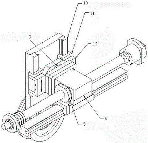
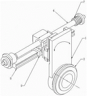
[0023] like figure 1 , 2 As shown, this embodiment provides a gapless arc swing mechanism based on a machine tool. The swing mechanism includes two transmission pairs: a rolling linear guide pair and a ball screw transmission pair. The two transmission pairs are connected by a second direction Central thrust combination bearing connection, through the cooperation of two transmission pairs, the linear motion generated by the ball screw is transformed into the arc swing motion of the terminal driven swing element, which completely eliminates the gap in the entire transmission chain and improves the transmission accuracy And rigidity and long-lasting precision retention.

[0024] The oscillating plate driven to perform reciprocating oscillating motion is connected with the fixed frame through the first thrust centripetal combined bearing, and the specific method is as follows: the inner ring of the first centripetal thrust combined bearing is fixedly connected with the oscillati...

Embodiment 2

[0030] In this embodiment, there is no swing guide plate, and there is only one second slider, and the two sides of the second slider are respectively installed on two guide rails, and its end faces are directly connected with the second centripetal thrust combined bearing, and the rest of the structure and implementation Example 1 is the same.

Embodiment 3

[0032] In this embodiment, another horizontal linear drive mechanism is used to replace the ball screw drive pair, which may include a guide rail fixed on the frame, and a slider installed on the guide rail. The slider also passes the second centripetal thrust The combined bearing is connected with the second slider or the swing guide plate, and the movement of the slider relative to the guide rail can be driven by a built-in motor. Its working principle is the same as that of Embodiment 1, so it will not be repeated here.


PUM


Abstract

The invention discloses a zero-clearance arc swing mechanism based on a machine tool. The zero-clearance arc swing mechanism based on the machine tool mainly solves the problems that in the prior art, assembly transmission clearances exist, and transmission accuracy is low. The zero-clearance arc swing mechanism based on the machine tool comprises a transverse linear drive mechanism, a vertical linear guide mechanism, a first centripetal thrust combination bearing (2) and a second centripetal thrust combination bearing (3). The transverse linear drive mechanism is connected with the vertical linear guide mechanism through the second centripetal thrust combination bearing (3), the vertical linear guide mechanism is installed on a driven swing element (1), and the first centripetal thrust combination bearing (2) is used for being connected with the driven swing element and a rack. The zero-clearance arc swing mechanism based on the machine tool thoroughly eliminates clearances of a whole transmission chain, improves transmission accuracy and rigidity, can achieve lasting accuracy retaining capability and effectively overcomes defects of the prior art.

Description

technical field [0001] The invention relates to a swing mechanism, in particular to a gapless circular arc swing mechanism based on a machine tool and a realization method thereof. Background technique [0002] In the prior art, in the field of machine tool processing technology, as long as it is a mechanism that performs an oscillating movement within ±45°, it uses a worm gear pair transmission or a gear pair transmission to realize the swing, which mainly has the following defects: (1) There is an assembly Transmission gap; (2) After long-term use, gaps will inevitably be generated due to sliding wear on the tooth surface, resulting in an increase in the backlash of the reciprocating swing and a decrease in transmission accuracy and stiffness. On the other hand, high-performance torque motors are expensive at the present stage, and their driving rigidity is not enough for heavy-load driving. Contents of the invention [0003] The object of the present invention is to ov...

Claims


Application Information

Patent Timeline
Patent Type & Authority Applications(China)
IPC IPC(8): F16H25/22
CPCF16H25/2209
Inventor 肖红陈春莫春林梁吉平李知密梁斐然李盼
Owner 成都煜鼎特种加工技术有限公司
Why Eureka
Try Eureka