Gas-sound complex field uniform-distribution device and uniform-distribution method thereof
A composite field and sound-generating device technology, which is applied in the direction of combustion method, combustion product treatment, solid residue removal, etc., can solve the problem of difficult to achieve uniform airflow, optimal opening ratio, and optimal hole shape are difficult to determine, etc. problem, to achieve the effect of enhanced sound energy, improved uniform distribution effect, and reduced loss
- Summary
- Abstract
- Description
- Claims
- Application Information
AI Technical Summary
Problems solved by technology
Method used
Image
Examples
Embodiment 1
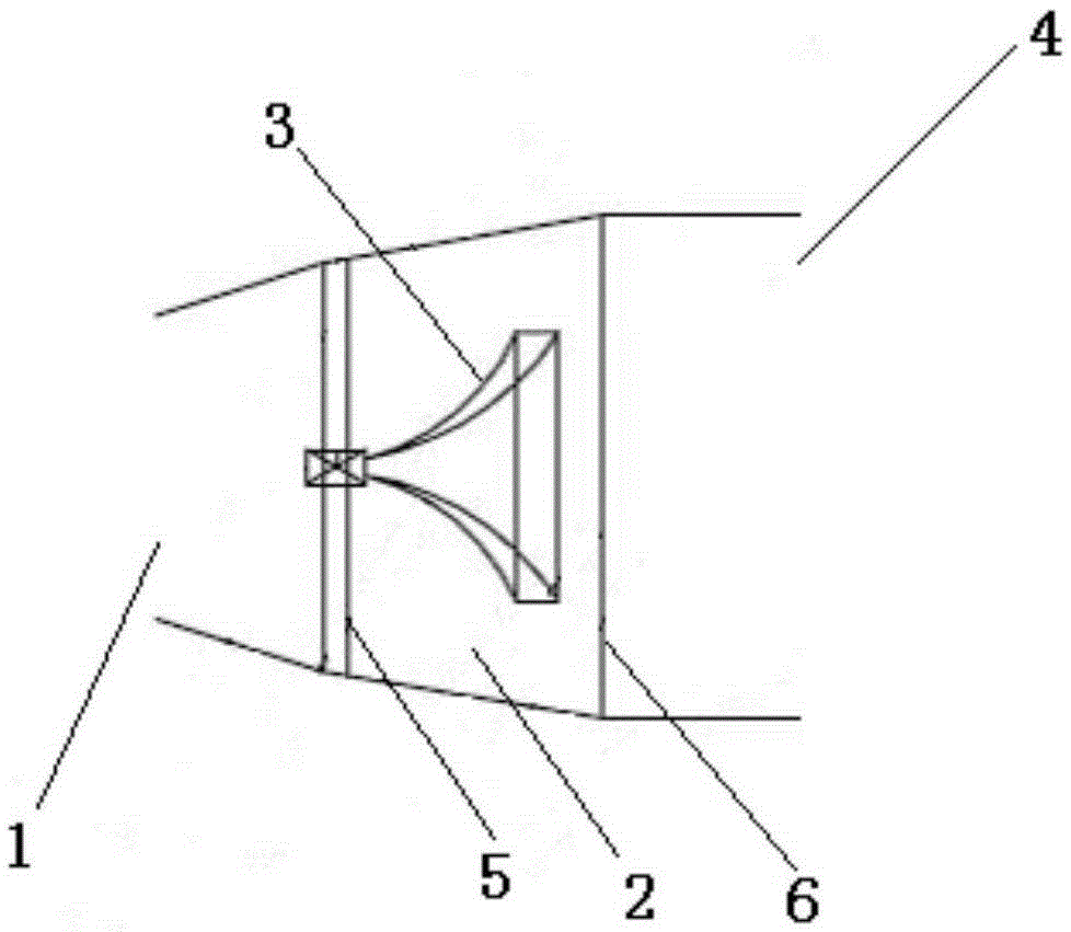
[0033] Such as figure 1 As shown, it is the aeroacoustic compound field uniform distribution device according to the present invention, which includes the device entrance 1, the aeroacoustic field distribution space 2, the sound generating device 3, and the device outlet 4, wherein the device inlet 1 is provided with an air intake plate 5 , the outlet 4 of the device is provided with an aeroacoustic deflector 6; the aeroacoustic equal field arrangement space 2 is a space enclosed by the air intake plate 5, the aeroacoustic deflector 6 and the space wall 7 between them; the sounding device 3 Set in the aeroacoustic uniform field layout space 2; the aeroacoustic uniform field layout space 2 is a space that gradually expands from the device inlet 1 to the device outlet 4, and this space can effectively form an aeroacoustic mixing field. When the airflow passes through the device inlet 1 When entering, the sound generating device 3 emits sound waves, which can form a good flow and...
Embodiment 2
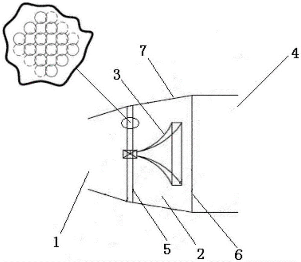
[0035] Such as figure 2 As shown, in this embodiment, the cross-section of the aeroacoustic averaging arrangement space 2 along the expanding direction is an isosceles trapezoid, wherein the space wall 7 between the aeroacoustic deflector 6 and the air inlet plate 5 is an isosceles trapezoid in cross section The waist of the air intake plate 5 and the air-acoustic deflector 6 are used as the bottom of the isosceles trapezoid; the corresponding side length ratio of the section formed by the air-acoustic deflector 6, the air intake plate 5 and the space wall 7 is 0.95-1.1:0.75 -0.85: 0.6-0.65. The air intake plate 5 is composed of two or more layers of plates, each of which has uniformly distributed holes, and there is a gap between adjacent two layers of plates, and the holes on adjacent two layers of plates are arranged in a dislocation . The aeroacoustic deflector 6 is provided with uniformly arranged holes.
[0036] The working process of the above device is as follows: ...
Embodiment 3
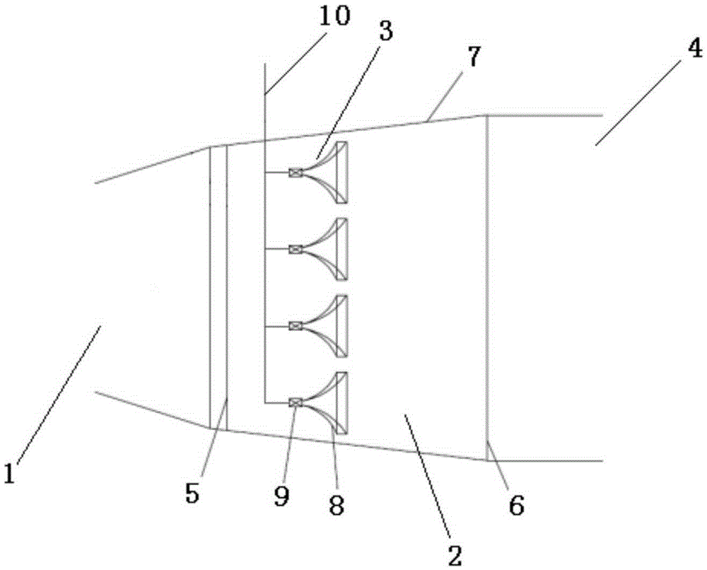
[0042] Such as image 3 As shown, the sound generating device 3 includes an acoustic conduit 8, an acoustic generator 9 and an air pipeline 10, wherein the acoustic conduit 8, the acoustic generator 9 and the air pipeline 10 are connected in sequence, and the air pipeline 10 is used to transport the sound of the acoustic generator 9. The working gas; the sounding direction of the sound conduit 8 faces the aeroacoustic deflector 6; the sounding frequency band and the sounding process of the sound generator 9 are controlled by the control system. Four sets of sounding devices 3 are provided. In actual use, high-frequency, intermediate-frequency or low-frequency sounding devices can be set according to different use needs, and sounding devices of different frequency bands can also be used in combination to improve work efficiency and work effect.
PUM
 Abstract
Description
Claims
Application Information
 - R&D
- Intellectual Property
- Life Sciences
- Materials
- Tech Scout
- Unparalleled Data Quality
- Higher Quality Content
- 60% Fewer Hallucinations
Browse by: Latest US Patents, China's latest patents, Technical Efficacy Thesaurus, Application Domain, Technology Topic, Popular Technical Reports.
© 2025 PatSnap. All rights reserved.Legal|Privacy policy|Modern Slavery Act Transparency Statement|Sitemap|About US| Contact US: help@patsnap.com


