Thyristor detector and thyristor detection method of the detector

A detection method and thyristor technology, applied in the field of thyristor detection and thyristor detector, can solve the problems of unsuitable high-power thyristor detection, inconvenient thyristor detection, long detection time, etc., achieve comprehensive and accurate detection, shorten maintenance time, and light weight Effect

Active Publication Date: 2018-07-20
MCC BAOSTEEL TECH SERVICE
View PDF5 Cites 0 Cited by
  • Summary
  • Abstract
  • Description
  • Claims
  • Application Information

AI Technical Summary

Problems solved by technology

[0004] In view of the shortcomings of the prior art described above, the object of the present invention is to provide a thyristor detector and a thyristor detection method of the detector, which are used to solve the problems of inconvenient thyristor detection, easy misjudgment of faults, and long detection time in the prior art. , low efficiency, not suitable for detection of high-power thyristors, etc.

Method used


Image

  • Thyristor detector and thyristor detection method of the detector
  • Thyristor detector and thyristor detection method of the detector
  • Thyristor detector and thyristor detection method of the detector

Examples


Embodiment 1

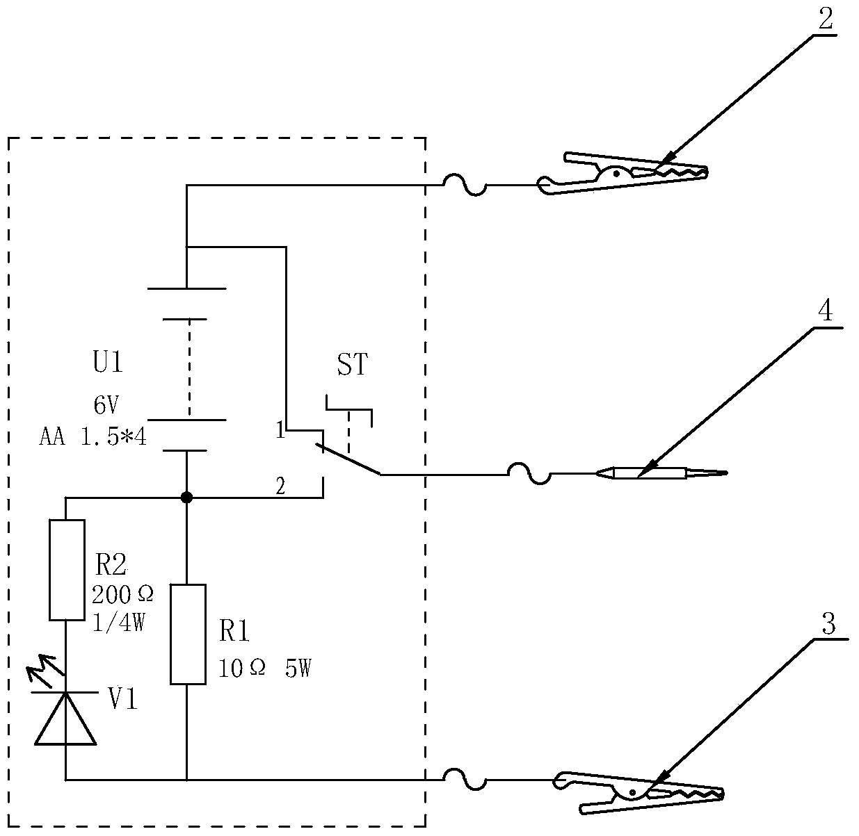
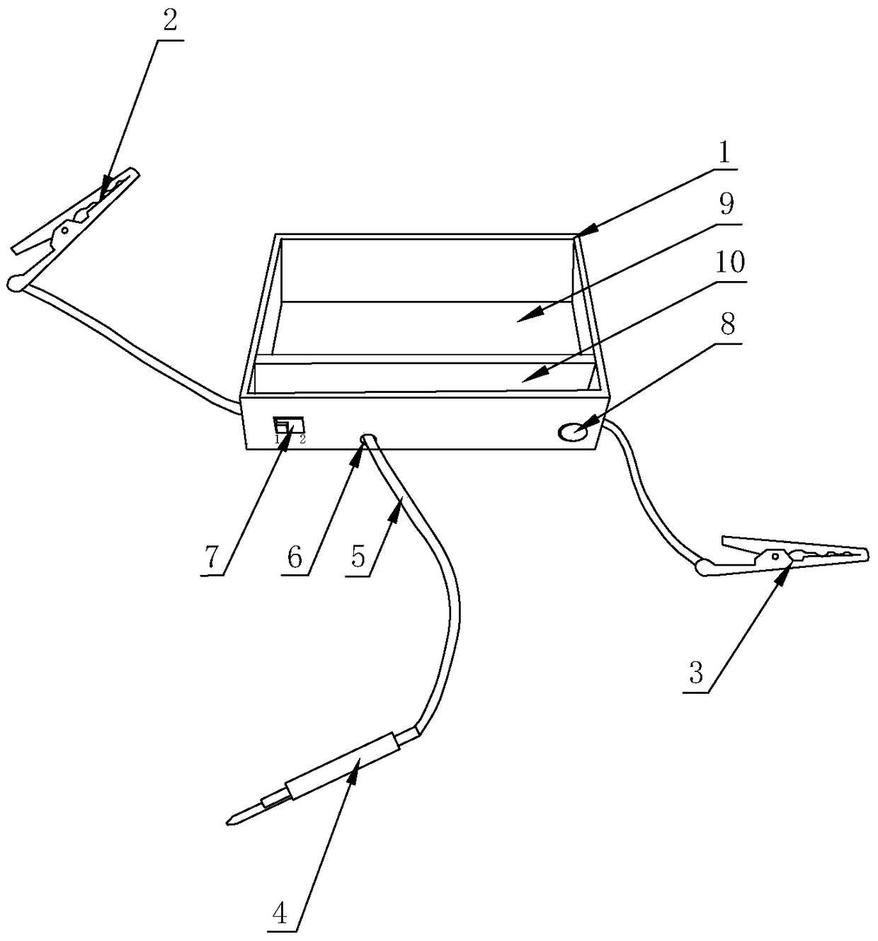
[0074] Such as Figure 1-2 As shown, a thyristor detector, the detector at least includes: a housing 1, a power supply, a load resistor R1, a light emitting diode V1, a light emitting diode current limiting resistor R2, a two-position switch ST, an anode clip 2, a cathode clip 3, The gate probe 4 and several wires 5; the shell 1 is a detachable cavity structure, and the left side, the right side and the middle part of the front side of the shell 1 are provided with wiring holes 6, and the front side of the shell 1 A switch installation hole 7 is provided at the left end, an indicator light installation hole 8 is provided at the front right end of the housing, and a battery slot 9 and a component slot 10 are provided in the housing cavity;

[0075] The power supply is set in the battery slot 9; the load resistor R1 and the light-emitting diode current-limiting resistor R2 are fixed in the component slot 10; the light-emitting diode V1 is installed in the installation hole 8 of ...

Embodiment 2

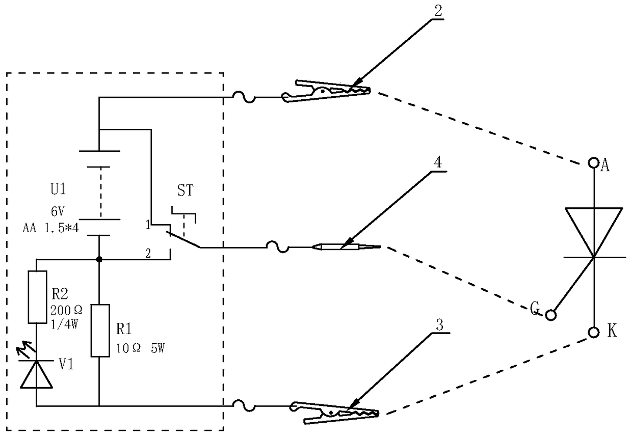
[0087] The connection method of ordinary thyristor detection circuit is as follows: image 3 As shown, the specific steps are as follows:

[0088] Step 1. Turn the two-position switch ST to the 1st gear contact;

[0089] Step 2, the anode clip 2 is connected to the anode A of the ordinary thyristor, and the cathode clip 3 is connected to the cathode K of the ordinary thyristor;

[0090] Step 3, the gate probe 4 touches the gate G of the ordinary thyristor;

[0091] Step 4. Analyze the results:

[0092] If the gate probe 4 does not touch the gate G of the ordinary thyristor and the light-emitting diode V1 lights up, then the anode A of the ordinary thyristor and the cathode K are short-circuited;

[0093] If the gate probe 4 does not touch the gate G of the ordinary thyristor, the light-emitting diode V1 does not light up, and the light-emitting diode V1 lights up and remains on after touching, then the ordinary thyristor is intact;

[0094] If the gate probe 4 does not tou...

Embodiment 3

[0096] The connection method of the bidirectional thyristor forward detection circuit is as follows: Figure 4 As shown, the specific steps are as follows:

[0097] Step 1. Turn the two-position switch ST to the 1st gear contact;

[0098] Step 2, the anode clamp 2 is connected to the second anode T2 of the triac, and the cathode clamp 3 is connected to the first anode T1 of the triac;

[0099] Step 3, the gate probe 4 touches the triac gate G3;

[0100] Step 4. Analyze the results:

[0101] If the gate probe 4 does not touch the gate G3 of the triac and the light-emitting diode V1 lights up, the anode and cathode of the triac are short-circuited;

[0102] If the gate probe 4 does not touch the gate G3 of the triac, the light-emitting diode V1 does not light up, and the light-emitting diode V1 lights up and remains on after touching, then the triac is intact;

[0103] If the gate probe 4 does not touch the gate G3 of the bidirectional thyristor, the light emitting diode V1 ...


PUM


Abstract

The invention provides a thyristor detector and a thyristor detection method of the detector. The detector includes a casing, a power supply, a load resistor, a light emitting diode, a light emitting diode current-limiting resistor, a two-bit change-over switch, an anode clamp, a cathode clamp, a gate pole probe, and a plurality of leads. The anode of the power supply is connected with the anode clamp, the cathode of the power supply is connected with the load resistor, the light emitting diode, and the light emitting diode current-limiting resistor, the light emitting diode current-limiting resistor is serially connected with the light emitting diode and then is parallelly connected with the load resistor, the light emitting diode and the load resistor are parallelly connected and then are serially connected with the cathode clamp, the two-bit change-over switch is connected with the anode and cathode of the power supply, and the gate pole is directly connected with the anode or cathode of the power supply via the two-bit change-over switch. The thyristor detector and the thyristor detection method of the detector solve the problems that in the prior art, the thyristor detection is convenient and is not suitable for the detection of large-power thyristors, the fault is easy to be misjudged, and the efficiency is low. The aims that the detector is small and portable, the detection method is simple and efficient in operation, and the application is wide are achieved.

Description

technical field [0001] The invention relates to the technical field of fault detection of electronic components, in particular to a thyristor detector and a thyristor detection method of the detector. Background technique [0002] Thyristors are widely used in various electronic equipment and electronic products, and are mostly used as controllable rectification, inverter, frequency conversion, voltage regulation, non-contact switches, etc. Once the thyristor is damaged, it will directly cause the equipment to fail to work. The maintenance and replacement of thyristors Most of them are carried out by on-site maintenance personnel. [0003] To detect whether the thyristor is good or bad, the field generally uses a multimeter to measure the resistance method, that is, after disconnecting the wiring of the thyristor, the measurement: the anode and the cathode are disconnected, the gate (control electrode) and the cathode are connected in one direction, and there are dozens to s...

Claims


Application Information

Patent Timeline
Patent Type & Authority Patents(China)
IPC IPC(8): G01R31/26
Inventor 陈刚王进忠张建军陈义
Owner MCC BAOSTEEL TECH SERVICE
Why Eureka
Try Eureka