Low-voltage current control circuit

A technology for controlling circuits and low-voltage currents, applied in control/regulation systems, regulating electrical variables, instruments, etc., can solve the problems of large output current fluctuations, narrow application range, complex structure, etc., and achieve high current output accuracy and current output The effect of wide range and simple circuit structure

Inactive Publication Date: 2016-01-27
ZHENGZHOU JINYUAN ELECTROMECHANICAL EQUIP ENG CO LTD
View PDF0 Cites 0 Cited by
  • Summary
  • Abstract
  • Description
  • Claims
  • Application Information

AI Technical Summary

Problems solved by technology

The low-voltage current control circuit in the prior art generally has complex structure, too large circuit, narrow application range, poor current stability, and large fluctuation of output current, which cannot meet some high requirements for current. Therefore, changing the low-voltage current control circuit Optimizing design and improvement to meet actual needs has become a problem that must be solved in front of technical personnel in the field

Method used


Image

  • Low-voltage current control circuit

Examples


Embodiment Construction

[0006] Below in conjunction with accompanying drawing, the present invention is described in detail.

[0007] In order to make the object, technical solution and advantages of the present invention clearer, the present invention will be further described in detail below in conjunction with the accompanying drawings and embodiments. It should be understood that the specific embodiments described here are only used to explain the present invention, not to limit the present invention.

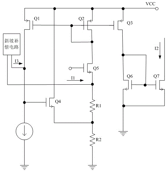
[0008] Such as figure 1 Shown is a schematic diagram of a low-voltage current control circuit of the present invention. A low-voltage current control circuit, including a slope compensation circuit, is characterized in that it also includes PMOS transistors Q1-Q3, NMOS transistors Q4-Q7, resistors R1 and R2, and a constant current source; the drain of the PMOS transistor Q1 is connected to the drain of the NMOS transistor Q4 One end of the gate and the constant current source, the source is conn...


PUM


Abstract

The invention discloses a low-voltage current control circuit which comprises the components of a slope compensating circuit, positive channel metal oxide semiconductors (PMOSs) Q1-Q3, negative channel metal oxide semiconductors (NMOSs) Q4-Q7, resistors R1 and R2, and a constant current source. The drain electrode of the Q1 is connected with the gate electrode of the Q4 and one end of the constant current source; the source electrode of the Q1 is connected with the drain electrode of the Q4, the source electrode of the Q2, the source electrode of the Q3 and a voltage source VCC; and the gate electrode of the Q1 is connected with the gate electrode of the Q2, the gate electrode of the Q3, the drain electrode of the Q2 and the drain electrode of the Q5. After R1 is connected with R2 in series, one end of an assembly obtained after connection is grounded, and the other end of the assembly is connected with the source electrode of the Q5. The source electrode of the Q4 is connected with the common end of the R1 and the R2. The drain electrode of the Q6 is connected with the drain electrode of the Q3, the gate electrode of the Q6 and the gate electrode of the Q7, and the source electrode of the Q6 is grounded. The other end of the constant current source is grounded. The other end of the Q7 is grounded. The first slope compensating current I1 of the slope compensating circuit is input into the source electrode of the Q5, and the second slope compensating current I3 of the slope compensating circuit is input into the source electrode of the NMOS Q5. The low-voltage current control circuit has beneficial effects of simple circuit structure, high current output precision, wide current output range and high output current stability.

Description

technical field [0001] The invention relates to a low-voltage current control circuit. Background technique [0002] In some control fields, the current requirements of the circuit have small fluctuations, good stability, and a large controllable range. The low-voltage current control circuit in the prior art generally has complex structure, too large circuit, narrow application range, poor current stability, and large fluctuation of output current, which cannot meet some high requirements for current. Therefore, changing the low-voltage current control circuit Optimizing design and improvement to meet actual needs has become a problem that must be solved in front of technical personnel in the field. Contents of the invention [0003] The object of the present invention is to provide a low-voltage current control circuit for the above-mentioned problems. The technical solution adopted in the present invention is as follows: a low-voltage current control circuit, includin...

Claims


Application Information

Patent Timeline
Patent Type & Authority Applications(China)
IPC IPC(8): G05F1/46
Inventor 刘言言
Owner ZHENGZHOU JINYUAN ELECTROMECHANICAL EQUIP ENG CO LTD
Why Eureka
Try Eureka