
Infrared polarization and light intensity image fusing method guided by multi-feature objective function

An objective function, infrared polarization technology, applied in the field of image fusion, can solve the problems of less consideration of guiding factors, poor quality of fusion image fusion, and low feature utilization.

Inactive Publication Date: 2016-01-27
ZHONGBEI UNIV
View PDF5 Cites 15 Cited by
  • Summary
  • Abstract
  • Description
  • Claims
  • Application Information

AI Technical Summary

Problems solved by technology

However, there are few existing image fusion algorithms based on differential evolution algorithms, and most of them are objective functions based on a single factor, such as gradient, mean value, degree of distortion, etc., and less consideration is given to the guiding factors of the image fusion process
[0004] The image feature is the reflection of the pixel value in the image and the relationship between the surrounding pixels, so the pixel in the image can reflect multiple features; if only one feature is selected for fusion, the information of other features will inevitably be weakened or even lost, and it cannot be fully fused source image features
Secondly, in the context of the existing infrared polarization image fusion research background, considering the fusion of image features, some of them are some fixed features determined in advance, and the common features and difference features are not distinguished according to different images, and some are not based on differences. The types of features and the strength and weakness of each other formulate corresponding fusion strategies, which leads to low utilization of features, poor fusion effect, and even some features are lost, some features are too strong, etc., which affect the final fusion effect phenomenon, resulting in poor fusion quality of the final fusion image

Method used


Image

  • Infrared polarization and light intensity image fusing method guided by multi-feature objective function
  • Infrared polarization and light intensity image fusing method guided by multi-feature objective function
  • Infrared polarization and light intensity image fusing method guided by multi-feature objective function

Examples


Embodiment Construction

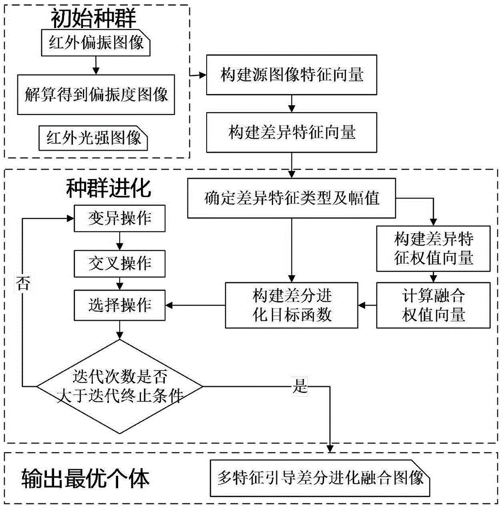
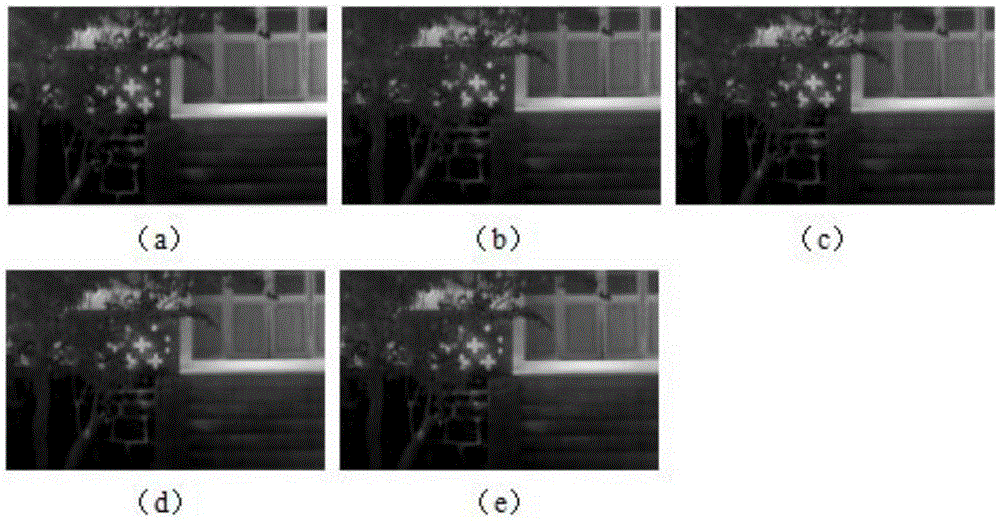
[0035] refer to figure 1 flow chart for figure 2 The infrared polarization and light intensity images shown are taken as an example to carry out experiments, and the specific implementation steps are as follows:

[0036] S1: Use the infrared thermal imager and infrared polarization camera to collect infrared light intensity and polarization images in the form of rotating filters. When shooting, the camera and the object are on the same horizontal plane. °, 90°, 135° polarization images;

[0037] S2: Using the registered four infrared polarization images of 0°, 45°, 90°, and 135° obtained in step S1, the corresponding polarization degree image and polarization angle image are obtained by solving the Stokes equation;

[0038] I = I 0 + I ...


PUM


Abstract

The invention belongs to the image fusing field, and specifically relates to an infrared polarization and light intensity image fusing method guided by a multi-feature objective function capable of comprehensively considering difference feature types and strong-weak relationship of a source image at several aspects and increasing the feature utilizing rate to improve the fusion effect. According to the invention, by utilizing the type and the amplitude of infrared polarization and light intensity image difference feature and an objective function established by a fusion weight vector, the strong-weak relationship between pixel multiple attributes is comprehensively considered; by utilizing features between source images as difference information between individuality of a group and by utilizing differential evolution to perform optimization fusion based on group differences, the fusion pertinence and the fusion effect of each feature are improved; the method has the several features of effectively improving the grey level, the texture, the edge and the contrast ratio in a fused imaged. The method is mainly used to fuse infrared polarization and light intensity images.

Description

technical field [0001] The invention belongs to the field of image fusion, and specifically relates to an infrared polarization and light intensity image fusion method guided by a multi-feature objective function, which can comprehensively consider the source image's multi-faceted difference feature type and strength relationship, and improve the feature utilization rate to enhance the fusion effect. Background technique [0002] Traditional infrared thermal imaging uses infrared radiation imaging, which is related to the temperature and emissivity of the target. The image outline is clear, but the contrast is low, the edge of the target is blurred, and the detail texture is weak, which can present the overall outline of the image; infrared polarization imaging is mainly through The target is imaged with the polarization characteristics of the background radiation energy, which is related to factors such as surface roughness, its own material, and geometry. It can detect targ...

Claims


Application Information

Patent Timeline
Patent Type & Authority Applications(China)
IPC IPC(8): G06T5/50
Inventor 杨风暴王肖霞原惠峰张雷董安冉赵艳霞
Owner ZHONGBEI UNIV
Learn More