Antenna structure of integrated pick-up head

An antenna structure and camera technology, applied in the direction of antenna support/installation device, etc., can solve problems such as difficult to achieve compatibility, unsatisfactory customer experience of navigation or wireless Internet access, etc., and achieve the effect of saving space and improving integration.

Inactive Publication Date: 2016-01-27
SHENZHEN SUNWAY COMM
View PDF6 Cites 15 Cited by
  • Summary
  • Abstract
  • Description
  • Claims
  • Application Information

AI Technical Summary

Problems solved by technology

Due to space constraints, the current solution can only be biased towards GPS or Wifi, which is difficult to achieve compatibility, resulting in unsatisfactory customer experience for navigation or wireless Internet access

Method used


Image

  • Antenna structure of integrated pick-up head
  • Antenna structure of integrated pick-up head
  • Antenna structure of integrated pick-up head

Examples


Embodiment 1

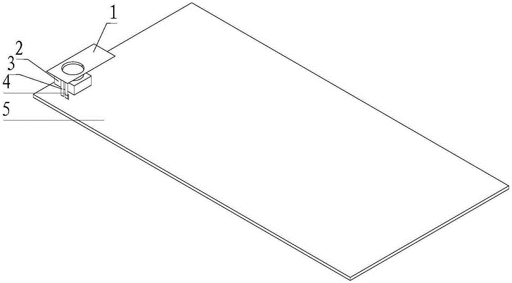
[0029] Please refer to figure 1 , Embodiment 1 of the present invention is:

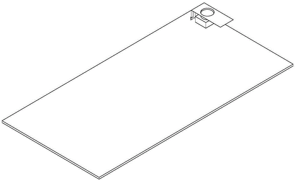
[0030] An antenna structure for an integrated camera, comprising a camera 2 and an antenna radiator 1, the antenna radiator 1 is arranged above the camera 2, and the antenna radiator 1 serves as a shielding cover for the camera 2 at the same time, that is to say, the antenna radiates The body 1 and the camera 2 shielding cover are the same part, which are integrated. The antenna uses the shape of the shielding cover and the grounding position to cooperate with the antenna to radiate, thus effectively reducing the occupied space. The antenna structure is suitable for electronic devices with cameras such as mobile phones and palmtop computers, such as figure 2 As shown, taking a mobile phone as an example, it can be set in the clearance area above the circuit board 5 . The antenna radiator 1 is preferably a BT antenna or a wifi antenna or a GPS antenna, the distance between the antenna radiator 1 an...


PUM


Abstract

The invention discloses an antenna structure of an integrated pick-up head. The antenna structure comprises a pick-up head and an antenna radiator. The radiator is arranged above the pick-up head. By means of the scheme provided by the invention, an antenna on wireless terminal equipment is further minimized, the integration level between the antenna and other wireless terminal devices is improved, the space of wireless equipment is saved to the greatest extent, and functions of an integrated device are free of influences.

Description

technical field [0001] The invention relates to the technical field of antennas, in particular to an antenna structure for an integrated camera. Background technique [0002] In an existing mobile terminal, in order to avoid interference to the camera, a shielding cover design is usually added. The antenna is an essential part of the mobile phone, and the camera shield is used to shield the interference signal of the camera; the wireless antenna is responsible for the transmission and reception of signals, and is a necessary part to realize wireless communication. Due to the relationship between the operating frequency and wavelength, the antenna also requires a certain space size. At present, the more common method is to make the wifi antenna and the GPS antenna into a two-in-one form, which will sacrifice their respective performances. Due to space constraints, the current solution can only be biased towards GPS or Wifi, and it is difficult to achieve compatibility, resu...

Claims


Application Information

Patent Timeline
Patent Type & Authority Applications(China)
IPC IPC(8): H01Q1/22
Inventor 陶昌虎毕晔海吴会林周仲蓉
Owner SHENZHEN SUNWAY COMM
Why Eureka
Try Eureka