
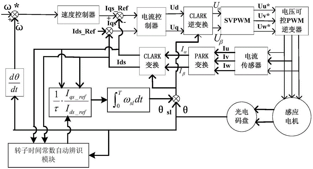
Method for automatically identifying asynchronous motor rotor time constant by frequency converter

A rotor time constant, asynchronous motor technology, applied in the direction of motor generator control, control generator, electronic commutation motor control, etc., can solve the influence of motor control effect, current, voltage measurement error, rotor time constant and actual value deviation And other issues

Active Publication Date: 2016-01-27
SHANGHAI STEP ELECTRIC +1
View PDF8 Cites 7 Cited by
  • Summary
  • Abstract
  • Description
  • Claims
  • Application Information

AI Technical Summary

Problems solved by technology

However, the mathematical model of the motor used in the algorithm is an idealized mathematical model. The motor model ignores many nonlinear factors for the convenience of calculation, resulting in a certain gap between the model and the actual situation of the motor, and there are errors in the current and voltage measurements. There is often a large deviation between the calculated rotor time constant and the actual value, which will affect the control effect of the motor

Method used


Image

  • Method for automatically identifying asynchronous motor rotor time constant by frequency converter
  • Method for automatically identifying asynchronous motor rotor time constant by frequency converter
  • Method for automatically identifying asynchronous motor rotor time constant by frequency converter

Examples


Embodiment 1

[0060] The method for automatically identifying the rotor time constant of an asynchronous motor according to Embodiment 1 includes the following steps:

[0061] Step a, calculate the approximate value τ of the rotor time constant according to the following formula;

[0062] τ = 1 ω e - ω r i s s 2 - i d s 2 i d s ;

[0063] Among them, ω e is the rated stator current angu...

Embodiment 2

[0076] The method for the inverter to automatically identify the rotor time constant of the asynchronous motor includes the following steps:

[0077] Step a, calculate the approximate value τ of the rotor time constant according to the following formula;

[0078] τ = 1 ω e - ω r i s s 2 - i d s 2 i d s ;

[0079] Among them, ω e is the rated stator current angular velocity...

Embodiment 3

[0092] The method for automatically identifying the rotor time constant of an asynchronous motor according to Embodiment 3 includes the following steps:

[0093] Step a, calculate the approximate value τ of the rotor time constant according to the following formula;

[0094] τ = 1 ω e - ω r i s s 2 - i d s 2 i d s ;

[0095] Among them, ω e is the rated stator current angu...


PUM


Abstract

The invention discloses a method for automatically identifying asynchronous motor rotor time constant by a frequency converter. The method comprises following steps: a, calculating the probable value tau of the rotor time constant; b, selecting at least five numbers including tau[1], tau[2] and the like...tau[n] between 0.1 tau to 3 tau as primary screening rotor time constants; c, driving the asynchronous motor to rotate by the frequency converter according to the selected first primary screening rotor time constant tau[1], and obtaining a first primary screening speed deviation accumulated value after the asynchronous motor finishing the operation process; d, obtaining a primary second screening speed deviation accumulated value based on a similar way of the step c; e, performing the same process until obtaining the n-th primary screening speed deviation accumulated value by the frequency converter; f, comparing the obtained n primary screening speed deviation accumulated values, and using the primary screening rotor time constant corresponding to the minimum primary screening speed deviation accumulated value as an identification result. Through adoption of the method, neither debugging performed by professional staff nor additional hardware equipment is needed, and the method has good identification effect.

Description

technical field [0001] The invention relates to a vector control technology of an asynchronous motor, in particular to a method for a frequency converter to automatically identify the rotor time constant of an asynchronous motor. Background technique [0002] At present, the vector control method of asynchronous motor can be divided into direct vector control method and indirect vector control method. The characteristic of the indirect vector control method is that the frequency converter controls the slip angular frequency of the asynchronous motor, and at the same time indirectly adjusts the excitation component current and the torque component current through the slip angular frequency. The control effect of the indirect vector control method depends on the motor parameters, especially the rotor time constant (ie L r / R r ). The direct vector control method does not depend on the rotor time constant, but it is difficult to accurately identify the flux vector, especiall...

Claims


Application Information

Patent Timeline
IPC IPC(8): H02P21/16
Inventor 张扬金辛海
Owner SHANGHAI STEP ELECTRIC
Learn More