
A polarization multiplexing direct detection system and method

A polarization multiplexing and detection system technology, applied in the field of optical communication, can solve problems such as complex system structure, application limitations, and high cost

Active Publication Date: 2017-09-29
UNIV OF SCI & TECH BEIJING
View PDF4 Cites 0 Cited by
  • Summary
  • Abstract
  • Description
  • Claims
  • Application Information

AI Technical Summary

Problems solved by technology

[0006] The technical problem to be solved by the present invention is to provide a polarization multiplexing direct detection system and method to solve the existing problems of complex system structure, high cost, or application limitations in the prior art

Method used


Image

  • A polarization multiplexing direct detection system and method
  • A polarization multiplexing direct detection system and method
  • A polarization multiplexing direct detection system and method

Examples


Embodiment 1

[0083] A polarization multiplexing direct detection system provided by an embodiment of the present invention includes: a laser, a first polarization beam splitter, a first intensity modulator and a second intensity modulator, a polarization beam combiner, a polarization maintaining coupler, a 45° Polarization rotator, second polarization beam splitter, third polarization beam splitter, 4 photodetectors and processor;

[0084] The first polarization beam splitter is used to split the light beam emitted by a laser into two orthogonal polarization states;

[0085] The first intensity modulator and the second intensity modulator are used to respectively perform intensity modulation of two analog electrical signals on two orthogonal polarization states;

[0086] The polarization beam combiner is used to synthesize the intensity-modulated two analog signals into a polarization multiplexing signal;

[0087] The polarization maintaining coupler is used to receive the synthesized pol...

Embodiment 2

[0159] The present invention also provides a specific implementation of a polarization multiplexing direct detection method. Since the polarization multiplexing direct detection method provided by the present invention corresponds to the specific implementation of the aforementioned polarization multiplexing direct detection device, the polarization multiplexing direct detection method The purpose of the present invention can be achieved by executing the process steps in the specific implementation of the above method, so the explanations in the specific implementation of the polarization multiplexing direct detection device above are also applicable to the specific implementation of the polarization multiplexing direct detection method provided by the present invention Embodiments will not be repeated in the following specific embodiments of the present invention.

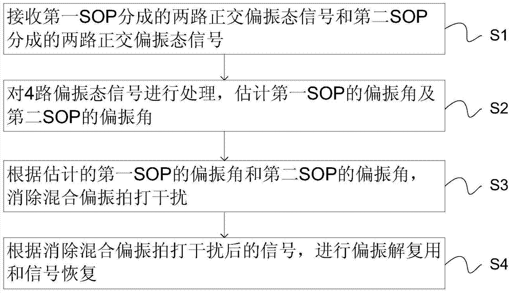
[0160] Such as figure 2 As shown, the embodiment of the present invention also provides a polarization multipl...


PUM


Abstract

The invention provides a polarization multiplexing direct detection system and method, which can double the transmission capacity of the system. The system includes: a first polarization beam splitter, used to split a beam emitted by a laser into two orthogonal polarization states; a first and a second intensity modulator, used to split two analog electrical signals into two Intensity modulation is performed on the orthogonal polarization state; polarization beam combiner is used to combine the intensity modulated signal into a polarization multiplexed signal; polarization maintaining coupler is used to combine the 45° polarization rotator to split the polarization multiplexed signal into two phase difference SOP with a fixed angle; the second and third polarization beam splitters are used to split the two SOPs into two orthogonal polarization signals; 4 photodetectors are used to convert the received 4 polarization signals Electrical signal; digital signal processor for estimating the polarization angles of the two SOPs, eliminating mixed polarization beating interference, and performing polarization demultiplexing and signal recovery. The invention is applicable to the technical field of optical communication.

Description

technical field [0001] The invention relates to the technical field of optical communication, in particular to a polarization multiplexing direct detection system and method. Background technique [0002] The rapid growth of network traffic continuously drives the demand for optical network bandwidth. Based on the use of powerful digital signal processing (DSP) and coherent detection technology, long-distance optical transmission has experienced rapid capacity improvement in recent years. However, unlike long-distance transmission networks, short-distance transmission is more sensitive to the cost of transceivers. Compared with the more costly coherent detection, the low-cost intensity-modulated direct detection technique is more attractive for short-distance transmission systems. In order to improve the single-wavelength optical transmission rate by using low-cost optical devices with limited bandwidth, a series of advanced modulation formats combined with intensity modula...

Claims


Application Information

Patent Timeline
Patent Type & Authority Patents(China)
IPC IPC(8): H04J14/06H04B10/54H04B10/532H04B10/66
Inventor 周娴闫凯丽霍佳皓刘伟隆克平
Owner UNIV OF SCI & TECH BEIJING
Learn More