
Circuit board automatic wiring machine

A technology of experimental boards and wiring machines, applied in the direction of electrical components, electrical components, etc., can solve the problems of long time to complete the work, complicated production process, affecting the operation of technicians, etc., to achieve time-consuming and labor-intensive, high accuracy, and precise placement Effect

Inactive Publication Date: 2019-02-01
艾合麦提·麦麦提
View PDF3 Cites 0 Cited by
  • Summary
  • Abstract
  • Description
  • Claims
  • Application Information

AI Technical Summary

Problems solved by technology

[0004] Disadvantages of existing technologies: 1. Users are required to be able to use software for drawing circuit diagrams; 2. The technology itself is very expensive; 3. User consumption is high; 4. The production process is complicated; 5. It takes a long time to complete the work
[0005] At present, in addition to using the above-mentioned PCB board making machine to make circuit boards, some handicraft methods can also be used to make circuit boards. Among them, it is most common to make circuit boards with electric soldering iron manual soldering, and almost no use of the above-mentioned machines to make PCB boards is done with electric soldering irons. Circuit board, but this method is very primitive. If you want to solder a more complicated or larger circuit, it will take a long time for one person to solder a board, which is time-consuming and laborious. More heat dissipation will affect the operation of the technician, and the process of soldering There will be a lot of smoke in the air, which is also harmful to human health

Method used


Image

  • Circuit board automatic wiring machine
  • Circuit board automatic wiring machine
  • Circuit board automatic wiring machine

Examples


Embodiment 1

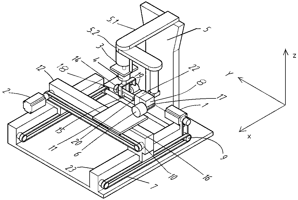
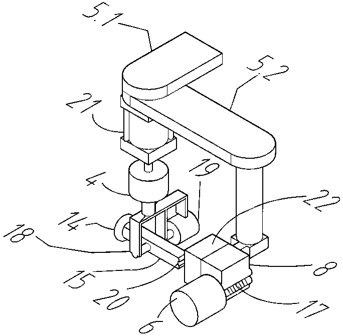
[0043] Embodiment 1, with reference to figure 1 , figure 2 , Figure 4 with Figure 5 : It includes a wiring manipulator and a breadboard moving mechanism for aligning the wiring manipulator;

[0044] The breadboard moving mechanism includes an x-axis movement mechanism and a y-axis movement mechanism for translating the breadboard 16 to be wired;

[0045] The x-axis moving mechanism includes an x-axis driving component for providing moving power, an x-axis transmission component connected to the x-axis driving component, and an x-axis moving component arranged on the x-axis transmission component;

[0046] The y-axis moving mechanism includes a y-axis driving component for providing moving power, a y-axis transmission component connected to the y-axis driving component, and a y-axis moving component arranged on the y-axis transmission component;

[0047] The y-axis driving part and the y-axis transmission part of the y-axis moving mechanism are fixed on the x-axis moving...

Embodiment 2

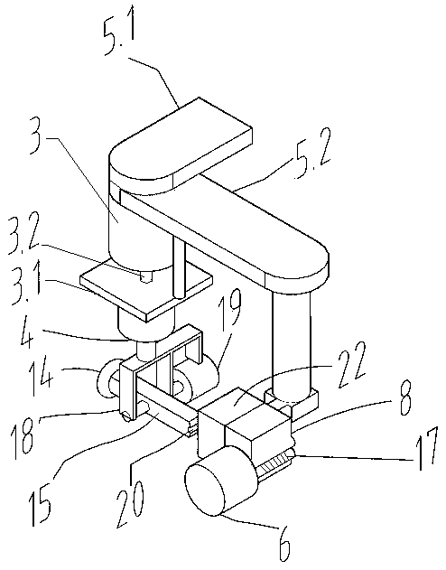
[0055] Embodiment 2, with reference to figure 1 , image 3 , Figure 4 with Figure 5 : the telescopic pressing mechanism is a pressing stepping motor 3 and a leading screw; the leading screw includes a screw 3.2 and a nut 3.1 moving up and down along the screw 3.2; the pressing stepping motor 3 is fixed below the pressing frame 5, And the output shaft of the pressing down stepper motor 3 is vertically downward, the screw rod 3.2 is coaxially connected with the output shaft of the pressing down stepping motor 3, and the wiring mechanism is fixed on the nut 3.1 for pressing down . Other technical characteristics are identical with embodiment 1.

Embodiment 3

[0056] Embodiment 3, with reference to Figure 1~Figure 5 : on the basis of embodiment 1 or embodiment 2, it further includes a feeding mechanism that delivers conductive wire 17 to magnetized metal rod 15 in the wiring mechanism, and the feeding mechanism includes winding wire stepping motor 6 and for The electric cutter 8 for cutting the conductive wire 17; the output shaft of the wire-wound stepper motor 6 is wound with a conductive wire 17, and the free end of the conductive wire 17 passes through the electric cutter 8 to the wiring mechanism 15 places in the magnetized metal rod.

[0057] Further, the electric cutter 8 includes an upper blade 8.2 and a lower blade 8.1 connected by a rivet; with the rivet as a boundary, a spring 8.3 is arranged between the upper blade 8.2 and the lower blade 8.1 on one side of the rivet, and a spring 8.3 on the other side of the rivet A connection wire 8.5 is provided between the upper blade 8.2 and the lower blade 8.1; one end of the con...


PUM


Abstract

The invention discloses an automatic wiring machine for a breadboard and belongs to the field of breadboard equipment manufacturing. The machine comprises a wiring mechanical hand and a breadboard moving mechanism for aligning the wiring mechanical hand. The breadboard moving mechanism includes an x-axis moving mechanism and a y-axis moving mechanism both used for translating a bread board. The y-axis moving mechanism is arranged on the x-axis moving mechanism. The breadboard is arranged on the y-axis moving mechanism. The wiring mechanical hand comprises a press-down bracket, a stretching press-down mechanism arranged under the press-down bracket, and a wiring mechanism arranged under the stretching press-down mechanism. The machine combines the wiring mechanical hand and the breadboard moving mechanism to achieve automatic wiring of the breadboard, improve the work efficiency, reduce the cost for manufacturing a circuit board, solve the rosin joint frequently generated in wiring by a user with electric iron, and solve the problems that wiring with electric iron is time-consuming and labor-consuming for a mechanic and waste gas generated during tin soldering is bad for health.

Description

technical field [0001] The invention relates to the field of circuit board manufacturing equipment, in particular to an automatic wiring machine for circuit experiment boards. Background technique [0002] In use, the circuit experiment board is also called a universal board or a universal board, and the wiring of the circuit experiment board is completed by connecting the independent pads on the circuit experiment board to each other. At present, the machines for making circuit boards mainly include photoplotters, CNC drills, exposure machines and etching machines. These machines are used to make PCB boards, and their price is about 100,000 yuan. factory. The current PCB boards are all drawn by users according to their own production circuit ideas with circuit design software such as Protel99SE, and then sent to special printing PCB board factories for printing. The factory charges are generally charged separately for proofing, photopainting and grid frame. Proofing is ch...

Claims


Application Information

Patent Timeline
Patent Type & Authority Patents(China)
IPC IPC(8): H05K13/06
Inventor 艾合麦提·麦麦提卡米力·麦麦提
Owner 艾合麦提·麦麦提
Learn More