
Nano-scale dynamic centrifugal separation device

A technology of centrifugal separation and separation device, which can be used in centrifuges and other directions to solve the problems of low separation efficiency and poor separation effect.

Inactive Publication Date: 2017-11-21
HENAN NORMAL UNIV
View PDF5 Cites 0 Cited by
  • Summary
  • Abstract
  • Description
  • Claims
  • Application Information

AI Technical Summary

Problems solved by technology

However, the existing separation devices generally use gap separators, which directly separate materials and grinding media, which not only has poor separation effect, but also has low separation efficiency.

Method used


Image

  • Nano-scale dynamic centrifugal separation device
  • Nano-scale dynamic centrifugal separation device

Examples


Embodiment Construction

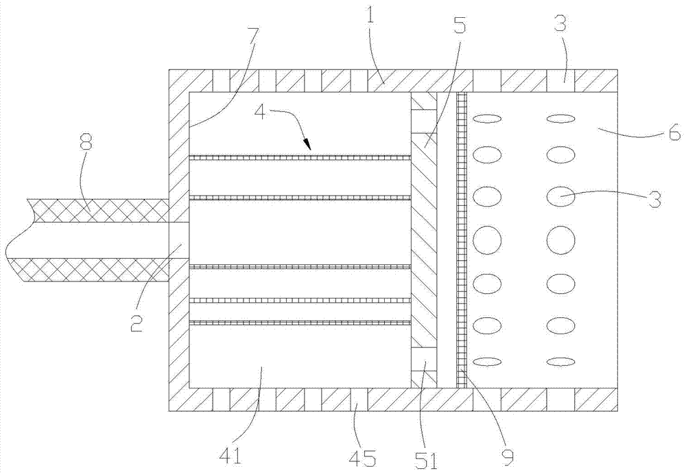
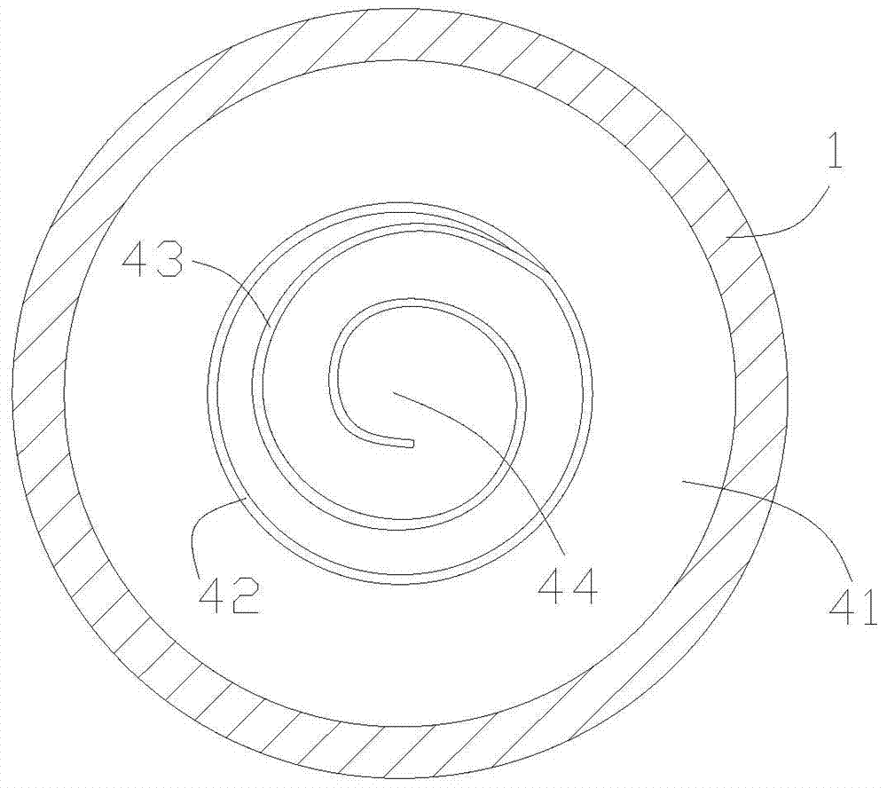
[0013] Combine below figure 1 , figure 2 Introduce in detail the nanoscale dynamic centrifugal separation device of the present invention, comprising a horizontally arranged separation cylinder 1 with one end open, the other end of the separation cylinder is closed, and a discharge port 2 is provided on the end face of the other end, and the other end of the separation cylinder is It is fixedly connected with the rotating discharge shaft 8, and the rotation of the discharge shaft drives the rotation of the separation cylinder to realize dynamic separation and improve the separation efficiency; the discharge port is connected with the inner cavity of the discharge shaft; the inner cavity at one end of the separation cylinder is covered with a screen 9. A separator 4 is fixed in the cavity at the other end of the separation cylinder, and the separation cavity of the separator communicates with the discharge port; the materials and grinding media flowing in from the one end of t...


PUM


Abstract

The present invention relates to the field of ball mills, specifically a nanoscale dynamic centrifugal separation device, which includes a horizontally arranged separation cylinder with one end open, the other end of the separation cylinder is closed, and a discharge port is opened on the end face of the other end. The other end is fixedly connected with the rotating discharge shaft, and the discharge port communicates with the inner cavity of the discharge shaft; the inner cavity of the one end of the separation cylinder is covered with a screen, and the other end of the separation cylinder is fixed with a separator. The separation chamber communicates with the discharge port. When the material in the grinding chamber and the grinding medium enter the pre-partition of the separation cylinder, the screen can block the grinding medium and the material with larger particles in the pre-partition to realize the pre-separation of the material; the pre-separated material with smaller particles enters the spiral The separation chamber of the shaped separator can realize multi-level separation and achieve nanoscale separation effect.

Description

technical field [0001] The invention relates to the field of ball mills, in particular to a separation device of a ball mill. Background technique [0002] Ball mill is widely used in paint, paint, rubber, abrasive, ceramics, ore, coal powder, metal powder, hard alloy, magnetic material, food, daily chemical, dye, ink, medicine, magnetic material, soft ferrite material, photosensitive Film and other industrial fields. Existing grinders include dry type and wet type. The working principle of the wet type ball mill is to use the stirring and grinding method. When the stirring shaft rotates at high speed, it drives the grinding medium called "sand" and the object to be ground (slurry) to make a vortex. Movement, so that the grinding medium moves from bottom to top along the inner cylinder wall under the action of centrifugal force, and falls down under the action of its own gravity when it reaches the liquid surface. During this process, the grinding medium moves back and for...

Claims


Application Information

Patent Timeline
Patent Type & Authority Patents(China)
IPC IPC(8): B04B5/10B04B7/00
Inventor 夏从新熊文奇杜娟王玉平
Owner HENAN NORMAL UNIV
Learn More