Gear clamping device of gear shaping machine

A technology of clamping device and gear shaping machine, which is applied in the direction of gear tooth manufacturing device, gear cutting machine, belt/chain/gear, etc., can solve the problem of low gear efficiency, achieve the effect of improving processing efficiency and reducing interval time

Inactive Publication Date: 2016-02-03
CHONGQING YUQING MACHINERY MFR
View PDF0 Cites 4 Cited by
  • Summary
  • Abstract
  • Description
  • Claims
  • Application Information

AI Technical Summary

Problems solved by technology

[0003] The present invention intends to provide a gear clamping device for gear shaping machines to solve the problem of relatively low efficiency in processing gears by gear shaping machines in the prior art

Method used


Image

  • Gear clamping device of gear shaping machine

Examples


Embodiment Construction

[0014] The present invention will be described in further detail below by means of specific embodiments:

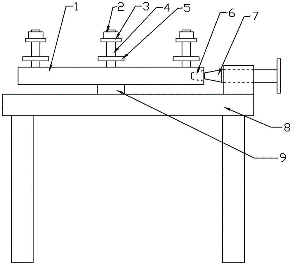
[0015] The reference signs in the accompanying drawings of the specification include: material bearing table 1, nut 2, slider 3, positioning column 4, stopper 5, limit hole 6, limit rod 7, frame 8, and rotating shaft 9.

[0016] Such as figure 1 The gear clamping device for the gear shaping machine shown includes a frame 8, a circular material receiving platform 1 is arranged above the frame 8, and a rotating shaft 9 is arranged between the material receiving platform 1 and the frame 8, and the axis of the rotating shaft 9 is in line with the The top surface of the bearing platform 1 is vertical. The top of rotating shaft 9 is welded with material receiving platform 1, and the bottom of rotating shaft 9 is connected with frame 8 by bearing. The side wall of the material bearing platform 1 is provided with a number of tapered limit holes 6, and the frame 8 is provided wi...


PUM


Abstract

The invention discloses a gear clamping device of a gear shaping machine. The gear clamping device comprises a rack, a bearing table is arranged above the rack, and a rotating shaft is arranged between the bearing table and the rack. The axis of the rotating shaft is perpendicular to the top face of the bearing table, the upper portion of the rotating shaft is fixedly connected with the bearing table, and the lower portion of the rotating shaft is rotatably connected with the rack. The bearing table is provided with a plurality of limiting holes, the rack is provided with limiting rods matched with the limiting holes, and the limiting rods and the rack are in threaded connection. At least two locating columns are arranged on the top of the bearing table, the axis of each locating column is parallel to the axis of the rotating shaft, and the locating columns are distributed in an annular array with the axis of the rotating shaft as the central line. The locating columns are rotatably connected with the bearing table, and fastening mechanisms used for pressing gears are arranged on the upper portions of the locating columns. The gear clamping device has the beneficial effect of improving the gear machining efficiency.

Description

technical field [0001] The invention relates to gear processing equipment, in particular to a gear clamping device for a gear shaping machine. Background technique [0002] A gear shaping machine is a device used to process spur gear teeth. Place the gear blank to be processed on the workbench. There is a rotating shaft on the upper part of the workbench. Set the gear blank on the rotating shaft. The gear shaping cutter of the gear shaping machine reciprocates up and down with the outer peripheral surface of the gear blank. The cutting movement, while rolling relative to the workpiece, process the gear teeth. Since there is only one rotating shaft on the workbench, it is necessary to shut down the gear shaping machine after processing a gear, then remove the gear, place a new gear blank on the workbench and fix it, and then start the gear shaping machine. processing. Due to the cutting action of the gear shaper cutter, the gear has just been machined. The temperature of t...

Claims


Application Information

Patent Timeline
Patent Type & Authority Applications(China)
IPC IPC(8): B23F23/06
Inventor 薛祖鑫
Owner CHONGQING YUQING MACHINERY MFR
Why Eureka
Try Eureka