Method for Resisting Welding of a First Component to a Second Component

A technology for resistance welding and components, which is applied in resistance welding equipment, energy storage discharge welding, welding power sources, etc., to achieve the effects of simplified method, simple cost, and cost reduction

Active Publication Date: 2016-02-03
ROBERT BOSCH GMBH
View PDF6 Cites 1 Cited by
  • Summary
  • Abstract
  • Description
  • Claims
  • Application Information

AI Technical Summary

Problems solved by technology

[0003] The problem underlying the invention is solved by the method according to claim 1 and by the device and the high-pressure fuel pump of the component co-claims

Method used


Image

  • Method for Resisting Welding of a First Component to a Second Component
  • Method for Resisting Welding of a First Component to a Second Component
  • Method for Resisting Welding of a First Component to a Second Component

Examples


Embodiment Construction

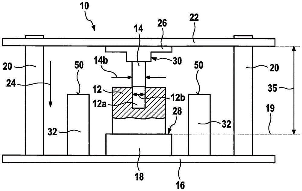
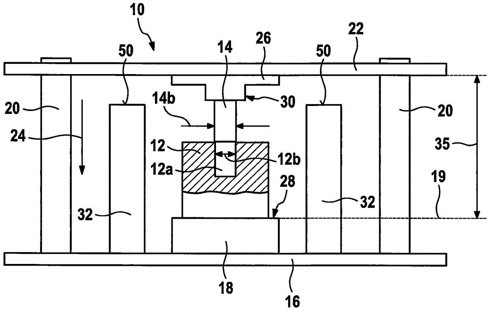
[0025] figure 1 A device 10 for resistance welding a first component 12 and a second component 14 is shown in a schematic sectional view. exist figure 1 The components shown in are arranged on a substrate 16, which is in figure 1 shown in the lower region of . The substrate 16 is presently embodied as a flat plate and is preferably an element of the device 10 .

[0026] Members 12 and 14 are made of metal and are electrically conductive. The first component 12 now has an opening 12 a which has an inner dimension 12 b in a direction perpendicular to an insertion direction 24 described below. The second component 14 has an outer dimension 14 b which is also defined perpendicularly to the insertion direction 24 and which is, for example, 0.1 mm to 1 mm (millimetres) larger than the inner dimension 12 b similarly to the press fit. The opening 12 a in the first component 12 represents, for example, an at least partially cylindrically shaped cavity. Correspondingly, the second...


PUM


Abstract

A method for resistance welding a first component to a second component including inserting the second component, at least by a connecting region, into an opening of the first component by a insertion distance and welding the first component to the second component in the process. An internal dimension of the opening and an external dimension of the connecting region are configured similar to a press fit with each other. The insertion distance is limited by an adjustable external distance limiter. A device is configured for resistance welding the first component to the second component, and a fuel high-pressure pump for fuel system of an internal combustion engine.

Description

technical field [0001] The invention relates to a method according to the preamble of claim 1 as well as a device and a high-pressure fuel pump according to the accompanying claims. Background technique [0002] Various welding methods are known on the market for connecting two metallic components to one another. For example, in automobile construction, parts of internal combustion engine components can be joined by means of laser welding. An alternative welding method can also be resistance welding, in which the individual welding partners are heated by means of an electric current. Contents of the invention [0003] The problem underlying the invention is solved by the method according to claim 1 as well as by the device and the high-pressure fuel pump of the component co-claims. Advantageous refinements are given in the subclaims. Features that are essential to the invention are also found in the following description and in the drawings, wherein individual features ...

Claims


Application Information

Patent Timeline
IPC IPC(8): B23K11/36B23K11/26F02M59/46
CPCB23K11/26B23K11/36F02M59/46B23K11/002B23K2101/006
Inventor J·埃希特迈尔G·舍希内S·考夫曼P·安德烈茨基
Owner ROBERT BOSCH GMBH
Why Eureka
Try Eureka