
A multi-layer mold press

A mold and press technology, applied in presses, manufacturing tools, etc., can solve the problems of long time, inconvenient operation, low production efficiency, etc.

Active Publication Date: 2017-03-29
瑞安市华大液压机械厂
View PDF7 Cites 0 Cited by
  • Summary
  • Abstract
  • Description
  • Claims
  • Application Information

AI Technical Summary

Problems solved by technology

The deficiencies in the prior art hydraulic press mainly include: 1. The ejection plate, the middle mold, the product removal, and the raw materials are generally carried out inside the press, and the operation safety is relatively poor. If all the above actions are carried out outside the press, the entire action The structure is complex, the operation is inconvenient, the production efficiency is low, and the labor intensity of the workers is high; 2. During the process of pressing the formed product, the press often needs to perform multiple mold exhausts in the closed mold state. At this time, the mold is required to be slightly opened to exhaust The distance allows the gas in the mold to be exhausted. If the press uses a multi-layer mold, then the multi-layer mold must be opened layer by layer for exhaust. The entire exhaust process takes a long time and the production efficiency is low.

Method used


Image

  • A multi-layer mold press
  • A multi-layer mold press
  • A multi-layer mold press

Examples


Embodiment Construction

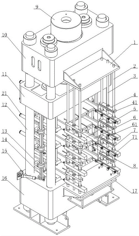
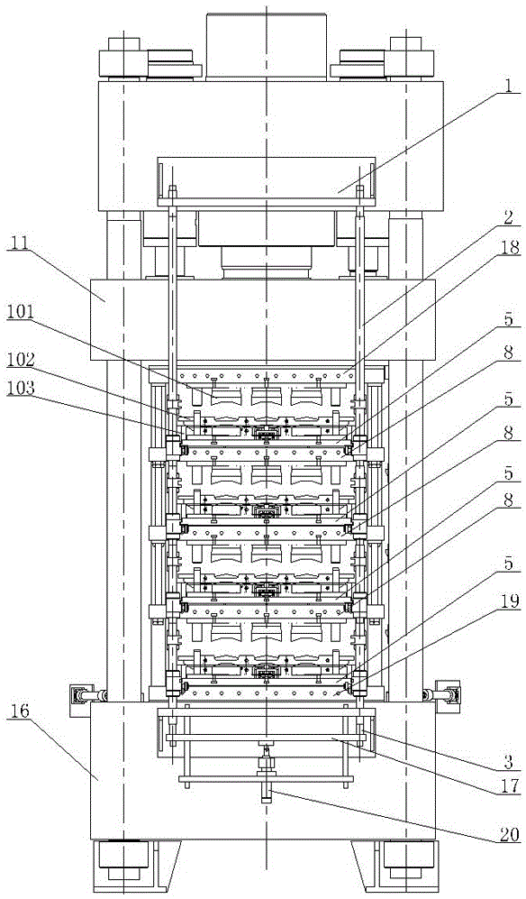
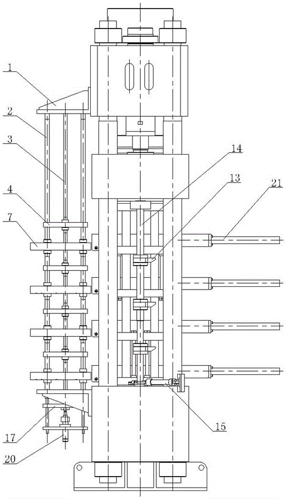
[0018] As shown in the figure, the multi-layer mold press of the present invention includes a lower machine base 16, a column 12, a top plate 10, a movable beam 11 and a synchronous exhaust mechanism for multi-layer molds, and the column 12 is fixedly installed on the lower machine base 16, and the top plate 10 Fixedly installed on the top of the column 12, the movable crossbeam 11 is set up and down under the top plate 10 and is pushed by the main oil cylinder 9, and the upper heating plate 18 arranged up and down between the movable crossbeam 11 and the lower machine base 16, three layers The middle heating plate 8 and the lower heating plate 19, the upper heating plate 18 is installed on the bottom of the movable beam 11, the lower heating plate 19 is installed on the lower machine base 16, and the middle heating plate 8 is movable up and down between the upper and lower heating plates. Sliding guide is carried out, the uppermost middle heating plate 8 is articulated below t...


PUM


Abstract

The invention discloses a multi-layer mold pressing machine. The multi-layer mold pressing machine comprises an upper heating plate, a plurality of middle heating plates and a lower heating plate, wherein the upper heating plate, the middle heating plates and the lower heating plate are vertically distributed. The multi-layer mold pressing machine is characterized in that mold pushing plates are arranged on the upper surfaces of the middle heating plates and the upper surface of the lower heating plate and connected with mold pushing air cylinders; inner guide plates are arranged on the left sides and the right sides of the mold pushing plates; a middle mold releasing mechanism is arranged in front of the heating plates and comprises a frame body, outer guide plates, mold releasing frames and a mold releasing oil cylinder; guide columns are arranged between the upper end and the lower end of the frame body, the outer guide plates are fixedly arranged on the guide columns, and outer guide grooves of the outer guide plates are aligned at inner guide grooves of the inner guide plates in the mold releasing state in a front-and-back manner; and the mold releasing frames are arranged above the outer guide plates in a vertically-movable manner, vertical movement of the mold releasing frames is pushed by the mold releasing oil cylinder, lateral grooves for supporting middle molds are formed in the mold releasing frames, and the groove width of the lateral grooves in the vertical direction is larger than the height of the lateral sides of the middle molds. The multi-layer mold pressing machine is high in production efficiency, the labor intensity of workers is reduced, the operation safety is improved, and the function of synchronous air discharging of multiple layers of molds can be achieved.

Description

technical field [0001] The invention relates to a hydraulic press equipment capable of simultaneously performing multi-layer mold pressing and forming. Background technique [0002] A hydraulic press is a machine that uses hydrostatic pressure to process metal, plastic, rubber, wood, powder and other products. It is often used in pressing and forming processes. Most of the hydraulic presses use a single-layer mold to press and form the product, but there are also two-layer or three-layer molds that simultaneously press and form the product. The deficiencies in the prior art hydraulic press mainly include: 1. The ejection plate, the middle mold, the product removal, and the raw materials are generally carried out inside the press, and the operation safety is relatively poor. If all the above actions are carried out outside the press, the entire action The structure is complex, the operation is inconvenient, the production efficiency is low, and the labor intensity of the wor...

Claims


Application Information

Patent Timeline
Patent Type & Authority Patents(China)
IPC IPC(8): B30B7/02B30B15/02B30B15/00
Inventor 宋新华朱瑞炜燕良恒
Owner 瑞安市华大液压机械厂
Learn More