
A separate spreading net

A separate and spread technology, applied in the direction of winding strip, thin material processing, transportation and packaging, can solve the problems of difficult processing, heavy overall weight, unfavorable assembly, etc., to reduce the difficulty of surface treatment and the difficulty of processing. Reduce and improve work efficiency

Active Publication Date: 2017-07-07
BULLMER ELECTROMECHANICAL TECH
View PDF7 Cites 0 Cited by
  • Summary
  • Abstract
  • Description
  • Claims
  • Application Information

AI Technical Summary

Problems solved by technology

Such a mechanism has the following defects: due to the limited contact area with the fabric, the tension of the fabric cannot be released to the maximum extent, and the spreading effect is not good
In order to improve this phenomenon, a one-piece spreading net was designed after improvement, but the length of the one-piece is too long, the requirements for processing technology and electroplating technology are too high, and the processing is difficult; at the same time, the overall weight is too heavy and It is not conducive to assembly and increases the difficulty of assembly

Method used

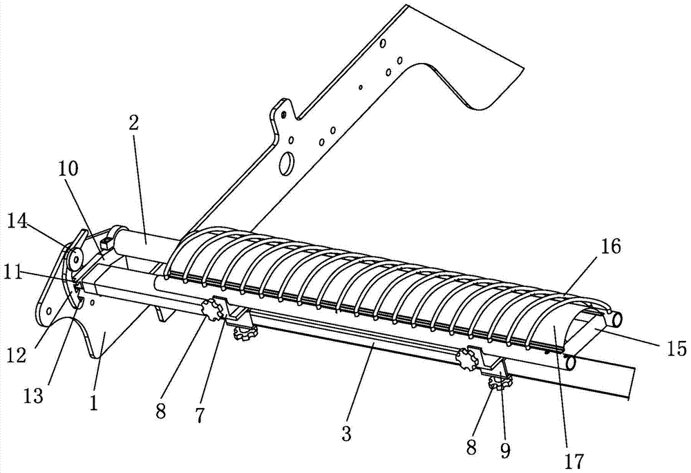

Image

  • A separate spreading net
  • A separate spreading net

Examples


Embodiment Construction

[0026] The present invention will be further described below with specific embodiment, see figure 1 -2:

[0027] A separate spreading net, comprising a left cloth table wall 1 and a right cloth table wall, a rotating shaft 2 is arranged between the left cloth table wall 1 and the right cloth table arm, and a spreading cloth is arranged on one side of the rotating shaft 2 The cloth net supporting arm 3, the spreading cloth net supporting arm 3 is also positioned between the left cloth table wall 1, the right cloth table arm. The spread net support arm 3 is connected to the rotating shaft 2 through the transfer mechanism, and the spread net support arm 3 is linked with the rotating shaft 2 through the transfer mechanism, that is, the rotating shaft 2 rotates, and at the same time drives the spread net support arm 3 to rotate around Axis 2 axis rotation. The transfer mechanism is connected with the inclination adjustment mechanism, and the inclination adjustment mechanism is se...


PUM


Abstract

The invention belongs to the field of cloth paving machines, and particularly relates to a separated cloth spreading net. A rotary shaft is arranged between a left cloth platform wall and a right cloth platform wall. A cloth spreading net supporting arm is arranged on one side of the rotary shaft and connected with the rotary shaft through a transfer mechanism and is in linkage with the rotary shaft through the transfer mechanism. The transfer mechanism is connected with a tilt angle adjustment mechanism. The tilt angle adjustment mechanism is arranged on the left cloth platform wall and the right cloth platform wall. One end of a left cloth spreading net body and one end of a right cloth spreading net body are arranged on the rotary shaft, and the other end of the left cloth spreading net body and the other end of the right cloth spreading net body are arranged on the cloth spreading net supporting arm. The left cloth spreading net body and the right cloth spreading net body are arranged in a spaced mode. The distance between the left cloth spreading net body and the right cloth spreading net body can be adjusted. The up-down tilt angles of the left cloth spreading net body and the right cloth spreading net body are adjusted by rotating the rotary shaft. According to the separated cloth spreading net, the working width of the left cloth spreading net body and the right cloth spreading net body can be adjusted according to the width of a fabric, and the distance and the tilt angle of the left cloth spreading net body and the right cloth spreading net body can be adjusted; the contact area of the cloth spreading net bodies can be adjusted according to different fabrics and placed at the bottom when not used, does not occupy much space and is easy and convenient to use.

Description

[0001] Technical field: [0002] The invention belongs to the technical field of spreading machines, in particular to a separate spreading net. [0003] Background technique: [0004] The intermediate spreading device on the existing spreading machine is realized by utilizing two groups of inclined inclined spreading wheels. Such a mechanism has the following defects: due to the limited contact area with the fabric, the tension of the fabric cannot be released to the greatest extent, and the spreading effect is not good. In order to improve this phenomenon, a one-piece spreading net was designed after improvement, but the length of the one-piece is too long, the requirements for processing technology and electroplating technology are too high, and the processing is difficult; at the same time, the overall weight is too heavy and It is not conducive to assembly and increases the difficulty of assembly. [0005] Invention content: [0006] The purpose of the present invention ...

Claims


Application Information

Patent Timeline
Patent Type & Authority Patents(China)
IPC IPC(8): B65H23/34
CPCB65H23/34B65H2301/51242
Inventor 何贤安余建军
Owner BULLMER ELECTROMECHANICAL TECH
Learn More