Caudal vertebra connecting structure for aeroengine

A technology of aero-engine and connecting structure, applied in the direction of machine/engine, jet propulsion device, etc., can solve problems such as endangering the safety of engine operation, intensifying the vibration of the tail vertebra, affecting the improvement of the vibration of the whole machine, etc., achieving long service life, reducing The effect of the number of connectors and the simple structure

Active Publication Date: 2016-02-03
AECC SHENYANG ENGINE RES INST
View PDF5 Cites 9 Cited by
  • Summary
  • Abstract
  • Description
  • Claims
  • Application Information

AI Technical Summary

Problems solved by technology

The additional hollow grooves processed on the surface of the flow channel of the tail cone to adapt to the assembly will directly cause a large disturbance when the airflow in the flow channel of the engine flows throu

Method used


Image

  • Caudal vertebra connecting structure for aeroengine
  • Caudal vertebra connecting structure for aeroengine
  • Caudal vertebra connecting structure for aeroengine

Examples


Embodiment Construction

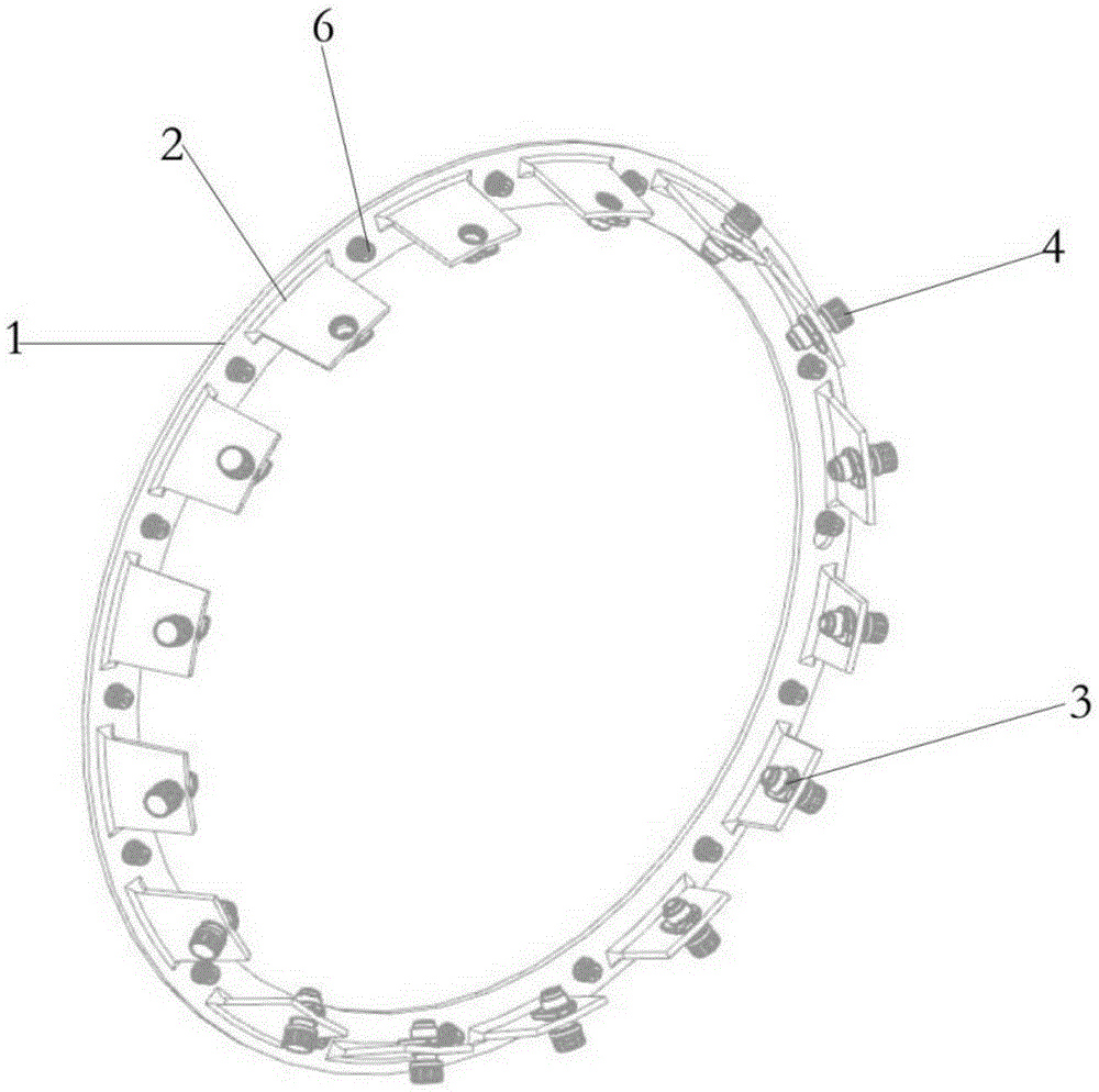
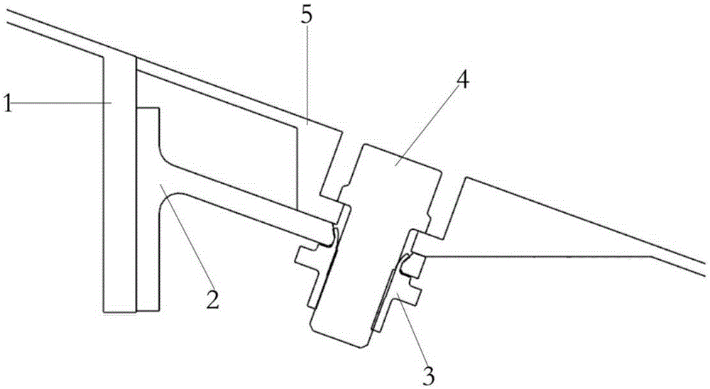
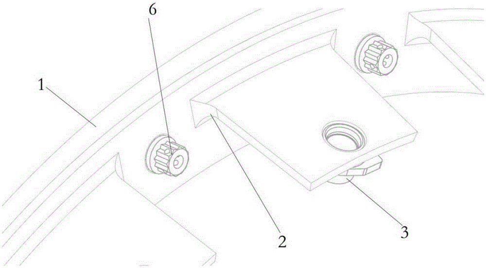
[0024] In order to better understand the aeroengine tail vertebra connection structure according to the scheme of the present invention, and to make the purpose, technical scheme and advantages of the present invention more clear, the following will describe the embodiment of the present invention in conjunction with the accompanying drawings in the embodiments of the present invention The technical solution is described in more detail. In the drawings, the same or similar reference numerals denote the same or similar elements or elements having the same or similar functions throughout. The described embodiments are some, but not all, embodiments of the invention. The embodiments described below by referring to the figures are exemplary and are intended to explain the present invention and should not be construed as limiting the present invention. Based on the embodiments of the present invention, all other embodiments obtained by persons of ordinary skill in the art without ...


PUM


Abstract

The invention discloses a caudal vertebra connecting structure for an aeroengine, and relates to the technical field of design of caudal vertebra connecting structures in aircraft structures; the caudal vertebra connecting structure for the aeroengine is used for reducing the disturbance and the vibration of air currents in the caudal vertebra connecting place of the aeroengine; a connecting edge of a caudal vertebra connecting bracket and a mounting bracket are formed to an integrally molded structure; the connecting edge is fixedly connected to a mounting edge of an engine turbine back receiver through a first bolt; the mounting bracket and the connecting edge are spaced on the connecting edge; a self-locking nut is arranged at one end, far from the connecting edge, of the mounting bracket; a second bolt fits the self-locking nut to fixedly connect a caudal vertebra with the engine turbine back receiver; and after the second bolt is tightened, the top surface of the head of the second bolt and the surface of a runner of the caudal vertebra are positioned on one surface. The caudal vertebra connecting structure for the aeroengine, provided by the invention, reduces the disturbance generated by the flowing of the air currents through the caudal vertebra, is convenient for structure machining, and is free of interference in the assembly and decomposition process; and the structure resists high temperature, is excellent in rigidity and higher in practicability, can be repeatedly used, is high in device stability, and is safe and reliable.

Description

technical field [0001] The invention relates to the technical field of design of a tail cone connection structure in an aircraft structure, in particular to a tail cone connection structure for an aero-engine, which is used to reduce airflow disturbance and vibration at the connection of an aero-engine tail cone. Background technique [0002] The tail cone, nozzle and mixer of the aero-engine constitute the engine exhaust functional unit. The various components are connected in sequence. The traditional tail cone is directly connected to the rear casing of the engine turbine at the front end by bolts. However, since the rear end of the tail cone is approximately closed, the bolts used to connect the tail cone must be in the flow channel of the tail cone. Several empty grooves are opened in the circumferential direction on the surface to meet the assembly space required by the fixing bolts. The additional hollow grooves processed on the surface of the flow channel of the tai...

Claims


Application Information

Patent Timeline
IPC IPC(8): F02K1/80
Inventor 怀时卫徐雪田大可
Owner AECC SHENYANG ENGINE RES INST
Why Eureka
Try Eureka