
Method for improving power generation efficiency of wind turbine unit

A technology of power generation efficiency and wind turbines, applied in wind energy generation, control of wind turbines, wind turbines, etc., can solve the problems of wind direction measuring instrument measurement deviation, non-consideration, highest level and loss of power generation, etc., to achieve high power generation, Improved power generation efficiency and accurate effect on wind

Inactive Publication Date: 2016-02-03
RENERGY ELECTRIC TIANJIN
View PDF6 Cites 16 Cited by
  • Summary
  • Abstract
  • Description
  • Claims
  • Application Information

AI Technical Summary

Problems solved by technology

[0003] In the existing technology, the wind turbines use the direct measurement value of the wind direction instrument to measure the wind, but the problem of measurement deviation caused by the wind direction measuring instrument due to the wake flow generated by the continuous rotation of the impeller after the wind turbine starts is not considered
[0004] The wind control based on the biased direct wind direction measurement results in the wind turbine not really facing the wind direction, so that the power generation efficiency of the wind turbine does not reach the expected maximum level and the loss of power generation

Method used


Image

  • Method for improving power generation efficiency of wind turbine unit
  • Method for improving power generation efficiency of wind turbine unit
  • Method for improving power generation efficiency of wind turbine unit

Examples


Embodiment Construction

[0021] It should be noted that, in the case of no conflict, the embodiments of the present invention and the features in the embodiments can be combined with each other.

[0022] The present invention will be described in detail below with reference to the accompanying drawings and examples.

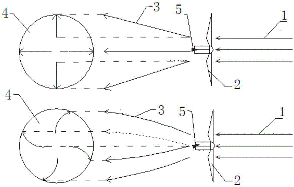
[0023] Such as Figure 1-3 as shown, figure 1 The upper part assumes that the actual wind direction remains unchanged, the upstream wind is evenly parallel, and when the wind rotor is stationary, at this time, viewed from the rear of the wind rotor, the wind is uniformly diffused, the downstream wind is evenly diffused, and the anemometer is correctly facing the wind; figure 1 The lower part is assuming that the actual wind direction remains unchanged, the upstream wind is evenly parallel, and when the wind rotor rotates, viewed from the rear of the wind rotor, the wind spreads in a spiral shape, and the downstream wind appears a spiral wake, which causes the anemometer to cause a devia...


PUM


Abstract

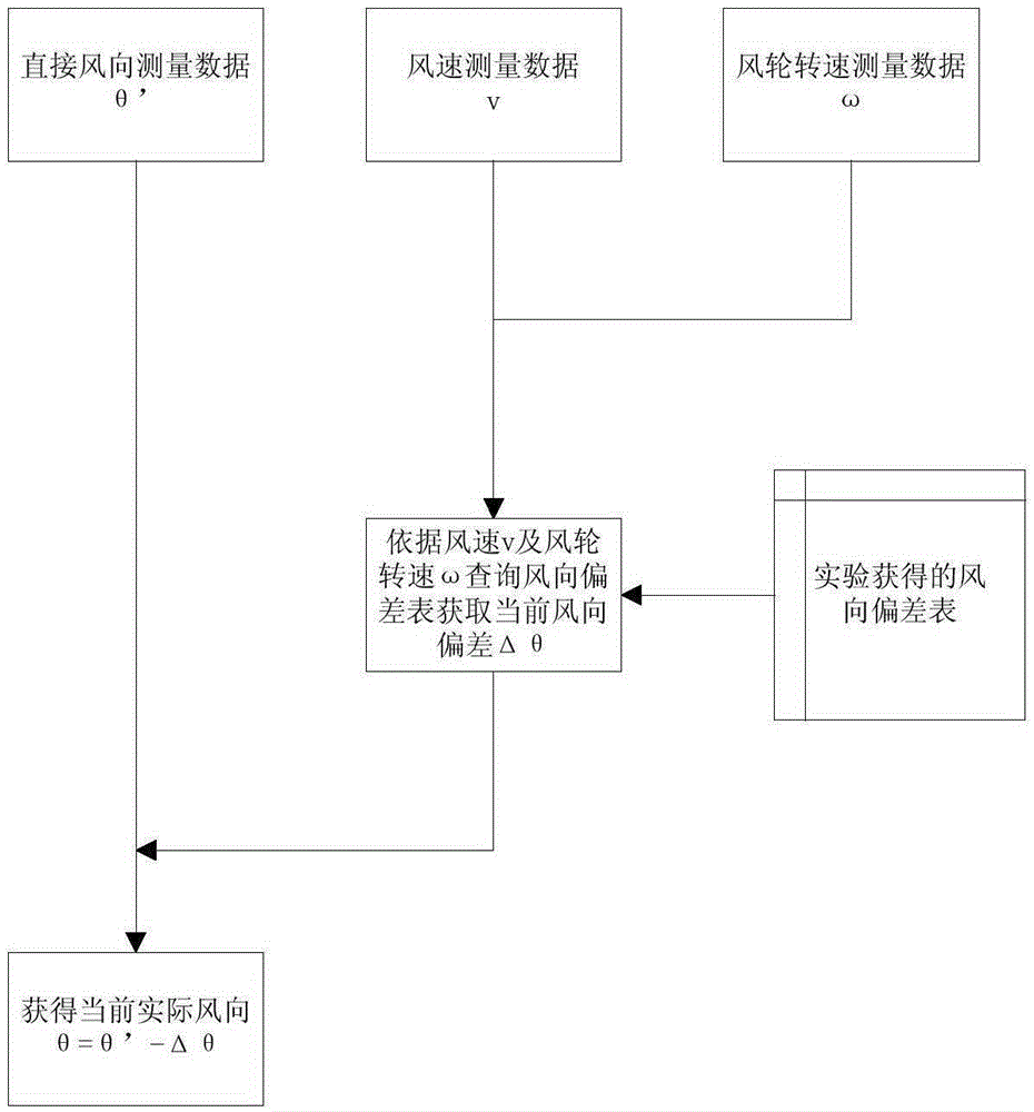
The invention provides a method for improving the power generation efficiency of a wind turbine unit. The method includes the steps that 1, statistical data of deviations delta theta nn generated by wind indicators, suffering from wake flow interference, under all wind speed sections vn and all impeller rotating speed sections omega n are measured; 2, the statistical data obtained in the step 1 are input into a database; 3, the current wind speed v and the current impeller rotating speed omega are measured, and the current wind direction theta' is measured; 4, according to the current wind speed v and the current impeller rotating speed omega measured in the step 3, the database is searched for the deviation delta theta generated by the wind indicators, suffering from wake flow interference, corresponding to the wind speed v and the impeller rotating speed omega, the actual wind direction theta is calculated according to the formula: theta=theta'-delta theta; and 5, the actual wind direction theta calculated in the step 4 serves as the actual wind direction to participate in wind turbine yaw control. Due to the fact that the wind direction deviations generated by the wind indicators, suffering from wake flow interference, at different wind speeds and different impeller rotating speeds are corrected, wind facing of the wind turbine unit is more accurate, the power generation efficiency of wind turbines is improved, and the power generation amount is higher.

Description

technical field [0001] The invention belongs to the technical field of wind power generation, and in particular relates to a method for improving the power generation efficiency of a wind turbine. Background technique [0002] The wind direction measuring instrument of the wind turbine is located behind the impeller. During the operation of the fan, it needs to face the wind in real time according to the wind direction measured by the wind direction measuring instrument, so as to ensure that the wind turbine is always facing the wind direction to obtain the maximum power generation efficiency. [0003] In the prior art, the wind turbine uses the direct measurement value of the anemometer to measure the wind, but does not consider the problem that the wind direction measuring instrument has measurement deviation caused by the wake generated by the continuous rotation of the impeller after the wind turbine is started. [0004] The wind control based on the biased direct wind d...

Claims


Application Information

Patent Timeline
IPC IPC(8): F03D7/02
CPCY02E10/72
Inventor 苏倩刘朋侯立军张新强
Owner RENERGY ELECTRIC TIANJIN
Learn More