Air Conditioning System

An air-conditioning system and interface technology, applied in the direction of compressors with reversible cycles, lighting and heating equipment, fluid circulation arrangements, etc., can solve problems such as reducing the performance of air conditioners, compressor damage, etc. The effect of increasing the amount of refrigerant

Active Publication Date: 2018-06-29
MIDEA GRP CO LTD +1
View PDF7 Cites 0 Cited by
  • Summary
  • Abstract
  • Description
  • Claims
  • Application Information

AI Technical Summary

Problems solved by technology

According to the characteristics of the air-injection enthalpy-enhancing compressor, if there is liquid refrigerant returning directly to the compressor, it will not only reduce the performance of the air conditioner, but also cause damage to the compressor

Method used


Image

  • Air Conditioning System
  • Air Conditioning System
  • Air Conditioning System

Examples


Embodiment 1

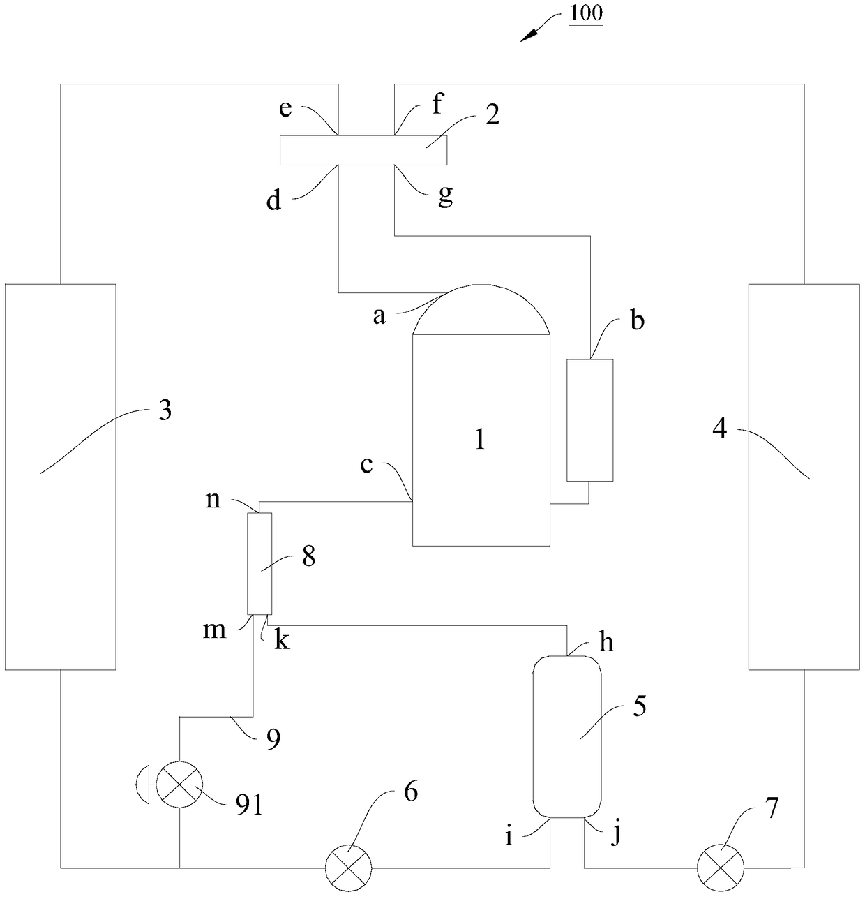
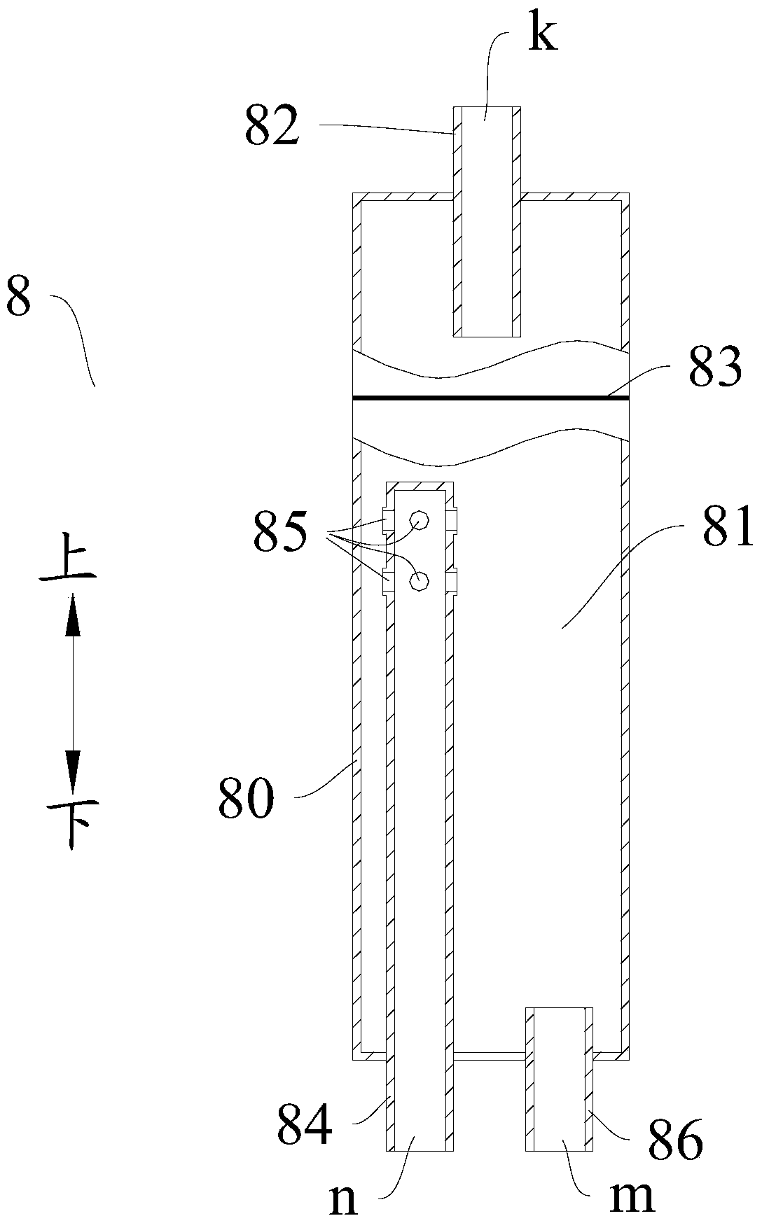
[0048] Such as figure 2 As shown, in this embodiment, the gas-liquid separator 8 includes: a housing 80 , an input pipe 82 , a filter 83 , an air outlet pipe 84 and a liquid outlet pipe 86 , wherein a separation space 81 is defined inside the housing 80 . The input pipe 82 protrudes from the top of the casing 80 into the separation space 81 , and the port of the input pipe 82 outside the casing 80 defines an input port k. The filter screen 83 is arranged in the separation space 81 and below the input pipe 82 to separate gas and liquid and filter impurities. The gas outlet pipe 84 extends from the bottom wall of the casing 80 into the separation space 81 , and the port of the gas outlet pipe 84 outside the casing 80 defines a gas output port n. The liquid outlet pipe 86 extends from the bottom wall of the housing 80 into the separation space 81 , and the port of the liquid outlet pipe 86 outside the housing 80 defines a liquid outlet m.

[0049] The port of the air outlet pi...

Embodiment 2

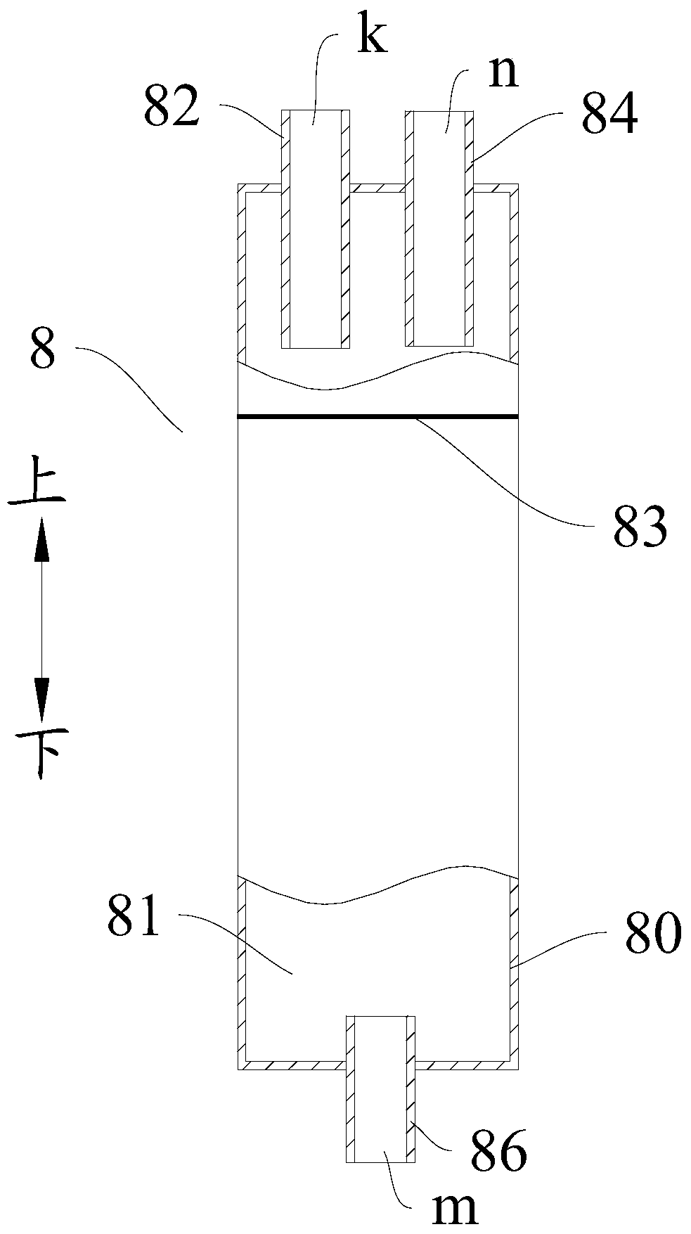
[0054] Such as image 3 As shown, in this embodiment, different from Embodiment 1, the air outlet pipe 84 protrudes from the top wall of the housing 80 into the separation space 81 and the lower end of the air outlet pipe 84 is located above the filter screen 83 .

[0055] In this embodiment, the gas-liquid mixed refrigerant that enters the separation space 81 from the input pipe 82 is separated from the gas and liquid under the double action of gravity and the filter screen 83, and the separated gas refrigerant enters from the lower end of the outlet pipe 84 into the The gas outlet pipe 84 enters the air outlet c from the gas outlet n, and the separated liquid refrigerant enters the liquid outlet pipe 86 from the upper end of the liquid outlet pipe 86 and is discharged from the liquid outlet m.

[0056] It should be noted that in this embodiment, other structures of the gas-liquid separator 8, such as the structure of the housing 80, the installation position of the input pip...


PUM


Abstract

The invention discloses an air-conditioning system, comprising: an air injection enthalpy increasing compressor, a reversing assembly, an indoor heat exchanger, an outdoor heat exchanger, a flash evaporator, a first throttling element, a second throttling element and a gas-liquid separator. The air injection enthalpy compressor includes an air injection port. The flash evaporator has a gas-liquid outlet, a first nozzle and a second nozzle, the first nozzle is connected with the indoor heat exchanger, and the second nozzle is connected with the outdoor heat exchanger. The gas-liquid separator has an input port, a gas output port, and a liquid output port. The input port is connected to the gas-liquid ejection port, the gas output port is connected to the gas ejection port, and the liquid output port is connected to the indoor heat exchanger and the first pipe port through a connecting pipe. The pipelines between them are connected, and a control valve is connected in series on the connecting pipe. According to the air-conditioning system of the present invention, the liquid refrigerant is prevented from directly returning to the air-injection enthalpy-increasing compressor through the air-injection port to cause damage to the air-injection enthalpy-increasing compressor, the amount of evaporated refrigerant is increased, and the performance and operation reliability of the air-conditioning system are improved.

Description

technical field [0001] The invention relates to the refrigeration field, in particular to an air conditioning system. Background technique [0002] At present, most air-conditioning systems that use air-jet enthalpy-increasing compressors use a flash evaporator to separate gas-liquid from the refrigerant condensed by the condenser, and the gaseous refrigerant returns directly to the compressor through the air jet port for compression. Thereby improving the performance of the air conditioner. According to the characteristics of the air injection enthalpy increasing compressor, if the liquid refrigerant returns directly to the compressor, it will not only reduce the performance of the air conditioner, but also cause damage to the compressor. Contents of the invention [0003] The present invention aims to solve one of the technical problems in the related art at least to a certain extent. Therefore, an object of the present invention is to provide an air-conditioning syste...

Claims


Application Information

Patent Timeline
Patent Type & Authority Patents(China)
IPC IPC(8): F25B13/00F25B43/00F25B41/04F25B41/06F25B41/20F25B41/34F25B41/37
Inventor 郑雄李金波
Owner MIDEA GRP CO LTD
Why Eureka
Try Eureka