
Large light-transmitting space enclosing structure heat transfer coefficient detection equipment and method

A technology of heat transfer coefficient and envelope structure, which is applied in the field of equipment for large-scale light-transmitting envelope structure heat transfer coefficient, can solve problems affecting indoor thermal comfort, increase air-conditioning energy consumption, and poor indoor thermal environment, etc., and achieve high detection The effect of improving precision and improving work efficiency

Inactive Publication Date: 2016-02-03
CHINA ACAD OF BUILDING RES
View PDF3 Cites 9 Cited by
  • Summary
  • Abstract
  • Description
  • Claims
  • Application Information

AI Technical Summary

Problems solved by technology

Poor thermal insulation performance of curtain wall not only wastes energy, but also may generate condensation, which will cause poor indoor thermal environment; poor thermal insulation performance of curtain wall not only greatly increases air conditioning energy consumption, but also affects indoor thermal comfort
The thermal performance of the curtain wall cannot meet the requirements of building thermal design, which will inevitably lead to CO 2 Emissions increase, resulting in urban air pollution, serious waste of building energy, and it does not conform to the national energy-saving policy
[0004] With the continuous development of building energy-saving work in my country, the design standards for building energy-saving are constantly improving, especially for the heat transfer coefficient of large-scale building curtain walls. Therefore, there is an urgent need to develop testing equipment and methods that can accurately test the heat transfer coefficient of large-scale light-transmitting enclosure structures.

Method used


Image

  • Large light-transmitting space enclosing structure heat transfer coefficient detection equipment and method

Examples


Embodiment Construction

[0010] The present invention will be further described in detail below in conjunction with the accompanying drawings and specific embodiments.

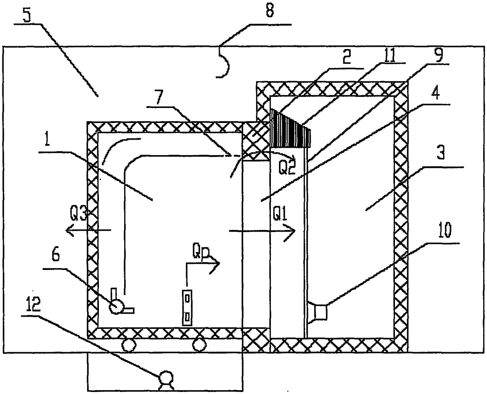
[0011] Such as figure 1 As shown, the hardware of the large-scale light-transmitting enclosure structure heat transfer coefficient detection equipment is mainly composed of an environmental chamber 5, a hot box 1, a specimen frame 2, a cold box 3, and a hoisting device 8, wherein the hot box 1 is also called "heat metering box", because all the temperature measuring points and power measuring points are placed on the side of the hot box 1. Compared with the cold box 3, in addition to the function of forming a specific temperature field and velocity field, the hot box 1 also needs to complete the entire The measurement function of the test process; in addition, in terms of software, the testing equipment also has an automatic control program and a data acquisition program. figure 1 middle, Q 1 is the heat transfer through the test pi...


PUM

PropertyMeasurementUnit
Thermal resistanceaaaaaaaaaa

Abstract

The invention provides a large light-transmitting space enclosing structure heat transfer coefficient detection equipment and method. The detection equipment mainly comprises an environmental chamber, a heat box, a test piece frame, a cold box, hoisting equipment and a data acquisition and automatic control device, wherein an air conditioning device is mounted in the environmental chamber, and the heat box, and the test piece frame, the cold box and the hoisting equipment are all arranged in the environmental chamber; the heat box is arranged to be movable, a power-driven structure is mounted at the bottom of the heat box, one side face of the heat box is provided with a door, and the heat box is internally provided with an adjustable-speed fan and an adjustable wind gap; one side of the test piece frame is fixedly connected with the cold box, and the other side is tightly matched with the heat box; the cold box is provided with an evaporator and auxiliary heating equipment; the hoisting equipment is located above the environmental chamber. A relatively simple structure and method are used to detect the heat transfer coefficients of large light-transmitting space enclosing structures with various sizes, and higher detection accuracy can be kept.

Description

technical field [0001] The invention relates to a large-scale building curtain wall heat transfer coefficient detection device and method, in particular to a device and method suitable for accurately detecting the heat transfer coefficient of large-scale light-transmitting enclosure structures of various sizes. Background technique [0002] Building curtain wall is an important part of public building envelope. Light-transmitting building components such as glass curtain walls are the weakest link in the thermal performance of building envelopes. The energy consumption of light-transmitting building components accounts for a considerable proportion of the energy consumption of the entire building. [0003] Statistics show that since the beginning of this century, the annual consumption of building curtain walls in my country over the years is the sum of the annual consumption of other countries in the world. With the further development of the economy, more and more glass c...

Claims


Application Information

Patent Timeline
IPC IPC(8): G01N25/20
Inventor 潘振周辉
Owner CHINA ACAD OF BUILDING RES
Learn More