Synchronization switch zero-crossing switching self-correction system and method

A zero-crossing switching and synchronous switching technology, applied in the field of distribution network, can solve the problem of inaccurate switching of magnetic latching relays, and achieve the effects of no inrush current input, improved accuracy, and suppressed mechanical interference

CN105305458AActive Publication Date: 2016-02-03NARI TECH CO LTD +1
4 Cites 6 Cited by

Patent Information

Authority / Receiving Office
CN · China
Current Assignee / Owner
Publication Date
2016-02-03

Smart Images

  • Figure 1
    Figure 1
Patent Text Reader

Abstract

The invention discloses a synchronization switch zero-crossing switching self-correction system. The system comprises a CPU, a control circuit, a remote signal detection circuit used for detecting whether a magnetic latching relay is closed or opened, and a sampling conditioning module used for acquiring a voltage and a current of a switch connection point of the magnetic latching relay. The invention further discloses a synchronization switch zero-crossing switching self-correction method. A closing or opening signal is emitted by the CPU to the magnetic latching relay at a moment, according to the closing or opening signal of the switch connection point of the magnetic latching relay detected by the remote signal detection circuit, closing time difference, opening time difference of the magnetic latching relay and time difference between closing and opening of the switch connection point of the magnetic latching relay and the coil signal are calculated, and the closing and opening time of the magnetic latching relay are corrected according to the three time differences and the voltage and the current of the switch connection point outputted by the sampling conditioning module. Through the system and the method, switching accuracy of a capacitor can be greatly improved, no-surge-current switching and no-arc breaking of the capacitor are realized.
Need to check novelty before this filing date? Find Prior Art

Description

technical field

[0001] The invention relates to a self-correcting system for zero-crossing switching of a synchronous switch, and also relates to a self-correcting method for zero-crossing switching of a synchronous switch, which belongs to the technical field of distribution networks. Background technique

[0002] The synchronous switch is a new type of dedicated reactive power compensation capacitor switching switch developed in recent years. It is the perfect combination of traditional mechanical switches and modern microelectronics technology. It absorbs the advantages of simple control structure of AC contactor, zero-voltage input and zero-current cut-off of composite switch, and perfectly solves the problems of high-voltage harmonics and large inrush current during capacitor switching. The synchronous switch is based on a single-chip microcomputer, supplemented by a high-precision sampling circuit and a reasonable program design to achieve an ideal zero-crossing switch...

Examples

Embodiment Construction

[0016] The present invention will be further described below in conjunction with the accompanying drawings. The following examples are only used to illustrate the technical solution of the present invention more clearly, but not to limit the protection scope of the present invention.

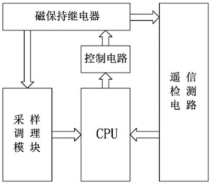
[0017] Such as figure 1 As shown, the self-correction system of synchronous switch zero-crossing switching includes CPU, control circuit, remote signal detection circuit and sampling conditioning module: the sampling conditioning module is used to collect the voltage and current of the switch contact terminal of the magnetic latching relay, and its signal output terminal is connected to the The signal input terminal of the CPU is connected; the control circuit is connected between the CPU and the magnetic latching relay. The relay action circuit is used to amplify the control signal output by the CPU to control the coil of the magnetic latching relay; the remote signal detection circuit is used...