LAA transmission method and device

A cell, target technology, applied in the communication field for unlicensed spectrum, can solve the problem of not being able to be transmitted

Active Publication Date: 2016-02-03
SHANGHAI LANGBO COMM TECH CO LTD
View PDF2 Cites 7 Cited by
  • Summary
  • Abstract
  • Description
  • Claims
  • Application Information

AI Technical Summary

Problems solved by technology

[0010] - If the given subframe is configured as a downlink subframe, it will cause SRS (SoundingReferenceSignal, listening reference signal) to be unable to be sent

Method used


Image

  • LAA transmission method and device
  • LAA transmission method and device
  • LAA transmission method and device

Examples


Embodiment 1

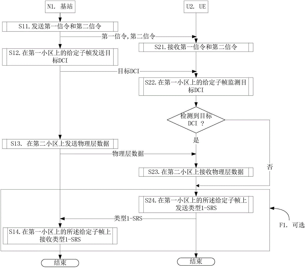
[0077] Embodiment 1 illustrates the flow chart of downlink physical layer data transmission, as attached figure 1 shown. attached figure 1 In , base station N1 is the serving base station of UEU2, and steps S14 and S24 identified in block F1 are optional steps.

[0078] For the base station N1, in step S11, send the first signaling to indicate that the given frame of the first cell is set to the first TDD UL / DL frame structure, and send the second signaling to indicate the second TDD UL / DL frame structure; in step S12 , sending target DCI in a given subframe in the given frame on the first cell; in step S13, sending physical layer data on the second cell according to the scheduling of the target DCI, where the target DCI is downlink scheduling DCI.

[0079] For UEU2, in step S21, receiving the first signaling determines that the given frame of the first cell is set as the first TDD UL / DL frame structure, and receiving the second signaling to obtain the second TDD UL / DL fram...

Embodiment 2

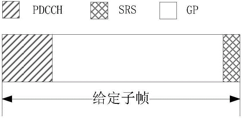
[0085] Embodiment 2 illustrates a schematic diagram of the given subframe in the present invention, as shown in the attached figure 2 shown. attached figure 2 , a given subframe is composed of three fields: a PDCCH field marked by a slash, a GP (GuardPeriod, guard interval) field marked by a blank, and an SRS field marked by a cross line.

[0086] The PDCCH domain includes X OFDM (Orthogonal Frequency Division Multiplexing, Orthogonal Frequency Division Multiplexing) symbols in the time domain, where X is a positive integer not greater than 4. The SRS domain includes one SC-FDMA (SingleCarrierFrequencyDivisionMultiAccess, Single Carrier Frequency Division Multiple Access) symbol in the time domain. The GP domain is used for conversion from downlink to uplink.

Embodiment 3

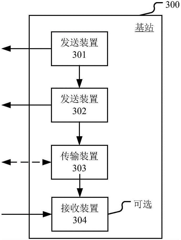
[0088]Embodiment 3 illustrates the structural block diagram of the processing device in the base station, as shown in the attached image 3 shown. attached image 3 Among them, the base station processing device 300 is composed of a sending module 301, a sending module 302, a transmitting module 303 and a receiving module 304, wherein the receiving module 304 is an optional module.

[0089] The sending module 301 is used to send the first signaling to indicate that the given frame of the first cell is set to the first TDD UL / DL frame structure, and is used to send the second signaling to indicate the second TDD UL / DL frame structure; the sending module 302 is used to The given subframe in the given frame on the first cell sends target DCI; the transmission module 303 is configured to send physical layer data on the second cell according to the scheduling of the target DCI—the target DCI is downlink scheduling DCI, Or it is used to receive physical layer data on the second ce...


PUM


Abstract

The invention provides a LAA transmission method and device. UE firstly receives a first signaling to determine that a given frame of a first cell is set to be a first TDD UL / DL frame structure, and receives a second signaling to obtain a second TDD UL / DL frame structure; a target DCI of a given sub-frame of the given frame in the first cell is monitored; wherein the given sub-frame corresponds to an uplink sub-frame of the first TDD UL / DL frame structure and an un-uplink sub-frame of the second TDD UL / DL frame structure, and the second signaling is a high-layer signaling or a physical-layer signaling. By adopting the technical scheme provided by the invention, the power consumption of the UE is saved, and meanwhile, unnecessary SRS abandonment is avoided; in addition, the invention is compatible with the existing eIMTA and CA protocols and has excellent compatibility.

Description

technical field [0001] The present invention relates to a communication scheme using unlicensed spectrum in a wireless communication system, in particular to a communication method and device for unlicensed spectrum (Unlicensed Spectrum) based on LTE (Long Term Evolution, Long Term Evolution). Background technique [0002] In the traditional 3GPP (3rdGenerationPartnerProject, Third Generation Partnership Project) LTE system, data transmission can only occur on the licensed spectrum. However, with the rapid increase of business volume, especially in some urban areas, the licensed spectrum may be difficult to meet the business volume. demand. The 62nd plenary meeting of 3GPPRAN (RadioAccessNetwork, wireless access network) discussed a new research topic, that is, research on unlicensed spectrum synthesis (RP-132085), the main purpose of which is to study the non-independent ( Non-standalone) deployment, the so-called non-independent means that the communication on the unlicen...

Claims


Application Information

Patent Timeline
Patent Type & Authority Applications(China)
IPC IPC(8): H04L5/00
Inventor 张晓博
Owner SHANGHAI LANGBO COMM TECH CO LTD
Why Eureka
Try Eureka