PCB and FPC welding method and surface mounting jig

A welding method and fixture technology, which is applied in the direction of assembling printed circuits, electrical components, and printed circuits with electrical components, can solve the problems of surface mount dislocation and other problems, and achieve high production efficiency, high reliability, and good consistency. Effect

Active Publication Date: 2016-02-03
广东德赛矽镨技术有限公司
View PDF8 Cites 19 Cited by
  • Summary
  • Abstract
  • Description
  • Claims
  • Application Information

AI Technical Summary

Problems solved by technology

[0003] However, because the small-sized FPC is a flexible material before reflow soldering, misalignment is prone to occur du...

Method used


Image

  • PCB and FPC welding method and surface mounting jig
  • PCB and FPC welding method and surface mounting jig
  • PCB and FPC welding method and surface mounting jig

Examples


Embodiment

[0029] Cooperate see Figure 1 to Figure 6 , a kind of PCB and FPC welding method of the present invention, comprises the following steps:

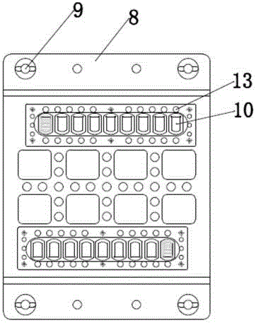
[0030] A. Install the PCB imposition on the patch fixture;

[0031] B. Solder paste printing or patching on the PCB imposition pad;

[0032] C. Take out the patch fixture with PCB imposition and place it flat on the mounting base;

[0033] D. Place the FPC that needs to be welded on the PCB layout through the patch fixture, so that there is printed solder paste between the PCB and the FPC welding area in each PCB layout;

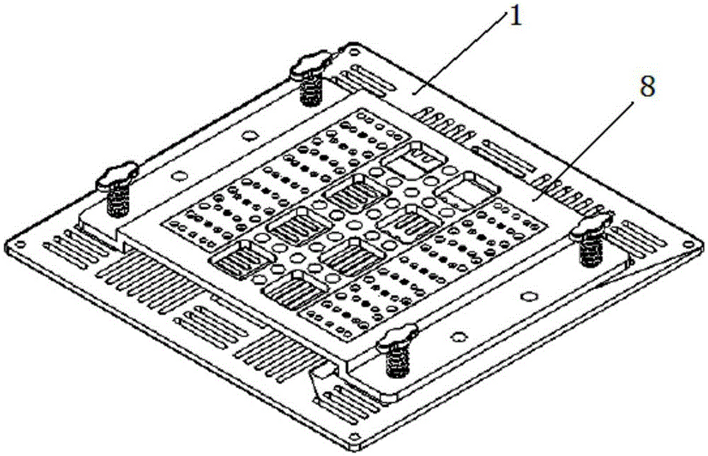
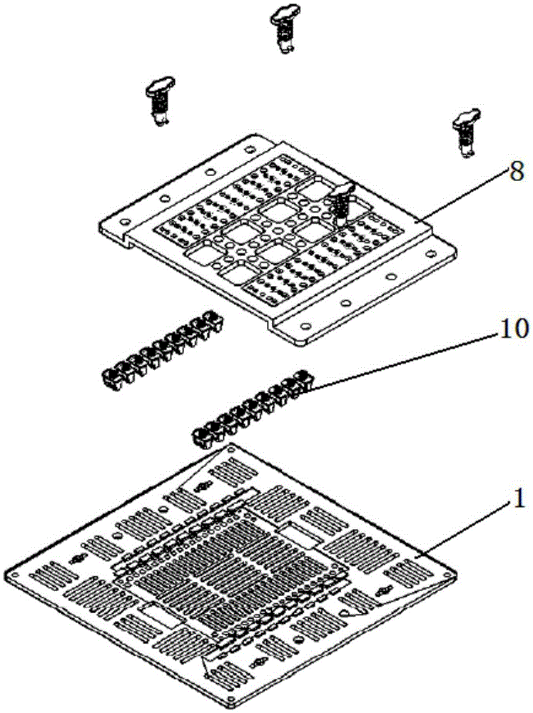
[0034] E. Assemble the press-fit cover on the mounting base, press the press-fit cover on the patch fixture and fix it;

[0035] F. Put the assembled board base, press-fit cover and patch fixture into the automatic reflow soldering furnace, so that the solder paste at the position where the PCB and FPC are attached is solidified after reflow soldering, and the soldering is completed.

[0036] Wherein, the patch fixt...


PUM


Abstract

The invention discloses a PCB and FPC welding method. The PCB and FPC welding method comprises the following steps that: PCB splicing boards are installed on a chip mounting fixture; solder paste printing or chip mounting is performed on pads of the PCB splicing boards; the chip mounting fixture with the PCB splicing boards is taken out and is flatly arranged on a board mounting base; FPCs requiring welding are arranged on the PCB splicing boards in a positioned manner through the chip mounting fixture, so that solder paste can be located between welding regions of PCBs and FPCs in each PCB splicing board; a pressing cover plate is assembled on the board mounting base, and the pressing cover plate is pressed and fixed to the chip mounting fixture and is fixed; and the assembled board mounting base, pressing cover plate and chip mounting fixture are arranged in an automatic reflow furnace, so that solder paste at attached positions of the PCBs and FPCs can be solidified through reflow soldering. The invention also provides a surface mounting jig used for the PCB and FPC welding method. The PCB and FPC welding method and the surface mounting jig of the invention have the advantages of high consistency in welding spots, high reliability, high production efficiency and no need for additional equipment investment.

Description

technical field [0001] The invention relates to the technical field of electronic products, in particular to a PCB and FPC welding method and a mounting fixture. Background technique [0002] With the development of smart phones, more and more lithium battery protection boards use FPC to paste connector output, but the cost of FPC is much more expensive than PCB, so the general lithium battery protection board adopts the structure of PCB and FPC welding to reduce the cost, that is A low-cost PCB is used for the main body of the board and an FPC is used for the connector output. In the FPC (FlexiblePrintedCircuit abbreviation, also known as flexible circuit board, flexible printed circuit board, flexible circuit board) and PCB (printed circuit board) welding technology, the welding methods are mainly manual alignment welding and HOTBAR thermocompression welding two ways. For products with high precision requirements for placement in large quantities, manual alignment weldin...

Claims


Application Information

Patent Timeline
IPC IPC(8): H05K3/36
CPCH05K3/363H05K2201/049
Inventor 钟志聪张伟张修坤
Owner 广东德赛矽镨技术有限公司
Why Eureka
Try Eureka