Die-casting machine punch lubricating machine

A technology of lubricating machine and die-casting machine, applied in the field of casting, can solve the problems of uneven size of lubricating particles, increase the production cost of die-casting, speed up the wear of punches, etc., and achieve the effect of accurate amount of lubricating particles, saving production cost and prolonging service life.

Active Publication Date: 2016-02-10
TAIZHOU SHENG WORLD MECHANICS
View PDF6 Cites 2 Cited by
  • Summary
  • Abstract
  • Description
  • Claims
  • Application Information

AI Technical Summary

Problems solved by technology

[0003] In the current production, the particle lubricator is generally used to add oily lubricating particles to lubricate the punch. The existing particle lubricating machine generally blows the oily lubricating particles to the gap between the punch and the pressure chamber of the die-casting machine through a hose with an air blowing device. Due to the high temperature of the pressure chamber, the oily particles will form a layer of oil film on the inner surface of the pressure chamber after being heated and melted, so as to play a lubricating role when the punch is shot, so the accuracy of the amount of lubricating particles added directly affects the quality and quality of the die-casting product. Lubrication effect, insufficient addition will increase the resistance of the punch during die-casting and accelerate the wear of the punch, excessive addition will generate excess gas, and the gas will enter the product during die-casting to form pores that directly cause the quality of the die-casting product to be unqualified. The particle lubricating machine in the prior art tends to take uneven material when the size of the lubricating particle is uneven, damp or mixed with impurities, and it is greatly affected by the air pressure of the air source. The point is blown away again. When the accuracy of the amount of lubricating particles added cannot be guaranteed, the wear speed of the punch is accelerated, which affects the quality of the die-casting product, increases the cost of die-casting production, and the complex structure of the cylinder valve is prone to failure.

Method used


Image

  • Die-casting machine punch lubricating machine
  • Die-casting machine punch lubricating machine
  • Die-casting machine punch lubricating machine

Examples


Embodiment Construction

[0026] The following will clearly and completely describe the technical solutions in the embodiments of the present invention with reference to the accompanying drawings in the embodiments of the present invention. Obviously, the described embodiments are only some, not all, embodiments of the present invention. Based on the embodiments of the present invention, all other embodiments obtained by persons of ordinary skill in the art without making creative efforts belong to the protection scope of the present invention.

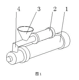
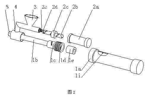
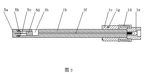
[0027] see Figure 1-7 , in one embodiment of the present invention, a punch lubricating machine for a die-casting machine, including a hopper 3, a retrieving mechanism, and a feeding mechanism, is characterized in that: the feeding mechanism includes a feeding cylinder 1, and the feeding cylinder 1 includes a feeding cylinder piston Rod 1b, feeding cylinder block 1a, feeding cylinder piston 1d, the hopper 3 is connected to the feeding pipeline 4, the tail end...


PUM


Abstract

The invention discloses a die-casting machine punch lubricating machine which comprises a hopper, a material taking mechanism and a feeding mechanism. The feeding mechanism comprises a feeding air cylinder, wherein the feeding air cylinder comprises a feeding air cylinder piston rod, a feeding air cylinder body and a feeding air cylinder piston. The hopper is connected to a material taking pipe, the tail end of the material taking pipe is connected with the material taking mechanism and is connected with the feeding air cylinder, the material taking pipe rightly faces a material tank led to the inside of the feeding air cylinder piston rod, a material taking device is arranged at the front section of the feeding air cylinder piston, a rotary fixed column is arranged inside the feeding air cylinder body, and the material taking device is matched with the rotary fixed column to drive the feeding air cylinder piston rod to perform whole material taking when the feeding air cylinder operates. The die-casting machine punch lubricating machine directly pours lubricating particles into lubricating position by using the material tank, can ensure that the adding amount of the lubricating particles is accurate and enables a punch to be fully lubricated, the service life of the punch is greatly prolonged, and the production cost is saved. In addition, the quality of a die-casting product is fully ensured, the problem that traditional feeding and blowing enable particles to be splashed all around is avoided, and the die-casting machine punch lubricating machine adopts an integral structure and is simple in structure, capable of saving space, convenient to install, low in fault rate and easy to maintain.

Description

technical field [0001] The invention relates to the technical field of casting, in particular to a punch lubricating machine for a die casting machine. Background technique [0002] During die casting production, the liquid metal flows into the mold cavity at high speed under the push of the injection punch, and then fills the cavity under high pressure and finally cools and forms. As the pressure chamber and the punch that are in direct contact with the liquid metal work at high temperature for a long time, the punch moves at a high speed relative to the pressure chamber during injection, and bears a large injection force. Therefore, in order to ensure that the punch completes the normal injection process and prolong the service life of the punch, lubrication must be carried out between the punch and the pressure chamber. [0003] In the current production, the particle lubricator is generally used to add oily lubricating particles to lubricate the punch. The existing part...

Claims


Application Information

Patent Timeline
Patent Type & Authority Applications(China)
IPC IPC(8): B22D17/20
Inventor 李文
Owner TAIZHOU SHENG WORLD MECHANICS
Why Eureka
Try Eureka