
A processing method for fuselage hafur surface

A processing method and fur surface technology, which are applied in the processing field of fuselage fur surface, can solve the problems of large tool loss, increased intermittent cutting degree, high economic cost, etc., and achieve the effect of reducing processing time.

Active Publication Date: 2018-11-13
西安陕柴重工核应急装备有限公司
View PDF4 Cites 0 Cited by
  • Summary
  • Abstract
  • Description
  • Claims
  • Application Information

AI Technical Summary

Problems solved by technology

[0005] 1. It is processed on a large-scale moving beam gantry boring and milling machine (machine tool table specification 2500x8000). The diameter of the extension head of the machine tool accessories exceeds φ200mm. To process the Huff surface and fillet of the fuselage, the tool diameter must exceed 200mm, while the diameter of the standard milling cutter is φ250mm , the diameter of the tool increases, the degree of intermittent cutting increases, the loss of the tool is large, and the economic cost also increases, which is not suitable for mass production purposes; and processing on large machine tools is a "big cow pulling a small cart", which is uneconomical
[0006] 2. Use fixed-beam gantry boring and milling machine (machine table specification 2040x6200 mm) for processing, usually use extended milling cutter handle, method 1 self-made milling cutter to extend the handle (length 380mm), more than 4D (the length of the tool and the minimum diameter of the tool D ratio), the length-to-diameter ratio is too large, and the tool is easy to vibrate, which cannot meet the machining accuracy requirements of the Hafur surface; method 2 uses the extended tool handle with ABS interface, and the connection between the equal-diameter intermediate module and the variable-diameter intermediate module meets the extended tool handle , but because the length is too long and the tool is too heavy, it cannot meet the roughness and shape tolerance of the Hafur surface
[0007] 3. The transition fillet R between the opening of the crankshaft hole of the fuselage and the Hafur surface is not easy to guarantee if the milling cutter and cutting parameters are not selected properly.

Method used


Image

  • A processing method for fuselage hafur surface
  • A processing method for fuselage hafur surface
  • A processing method for fuselage hafur surface

Examples


Embodiment Construction

[0040] The implementation of the present invention will be described in detail below in conjunction with the accompanying drawings and examples, so as to fully understand and implement the process of how to apply technical means to solve technical problems and achieve technical effects in the present invention. It should be noted that, as long as there is no conflict, each embodiment and each feature in each embodiment of the present invention can be combined with each other, and the formed technical solutions are all within the protection scope of the present invention.

[0041] Specifically, this method utilizes the extended shank of the milling cutter with good shock absorption effect, designs special φ160mm rough and fine milling cutters, selects appropriate cutting parameters, and uses the small-sized fixed-beam gantry boring and milling machine to refine the Hafur surface and rounded corners of the fuselage. for processing. Among them, the shock-absorbing milling cutter ...


PUM


Abstract

The invention discloses a method for machining the matched surface of a machine body. The method for machining the matched surface of the machine body comprises the step of rough milling, the step of semi-finish milling and the step of finish milling. According to the steps, a damping milling tool extension handle is selected for milling tool installation; one end of a damping milling tool rod is connected with the tool handle of a tool, and the other end of the damping milling tool rod is positioned through a mandrel and locked through an inner hexagon screw; the overhanging length of the tool is six times of the diameter of the tool so that machining of the matched surface can be completed, the planeness of the matched surface is 0.02 mm, the roughness is not lower than Ra1.6 microns, and the perpendicularity of two parallel surface perpendicular to the matched surface is 0.02 mm. By the adoption of the scheme, the time for machining the matched surface is shortened, and the cutting parameter can be increased by at least 50% generally; the method is a better option for the milling application of tools with the tool overhanging lengths being six times or more of the diameters of the tools.

Description

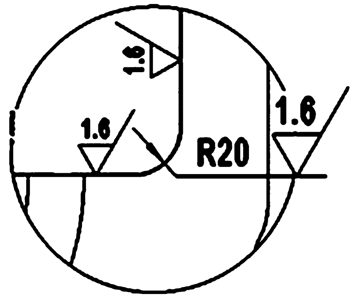
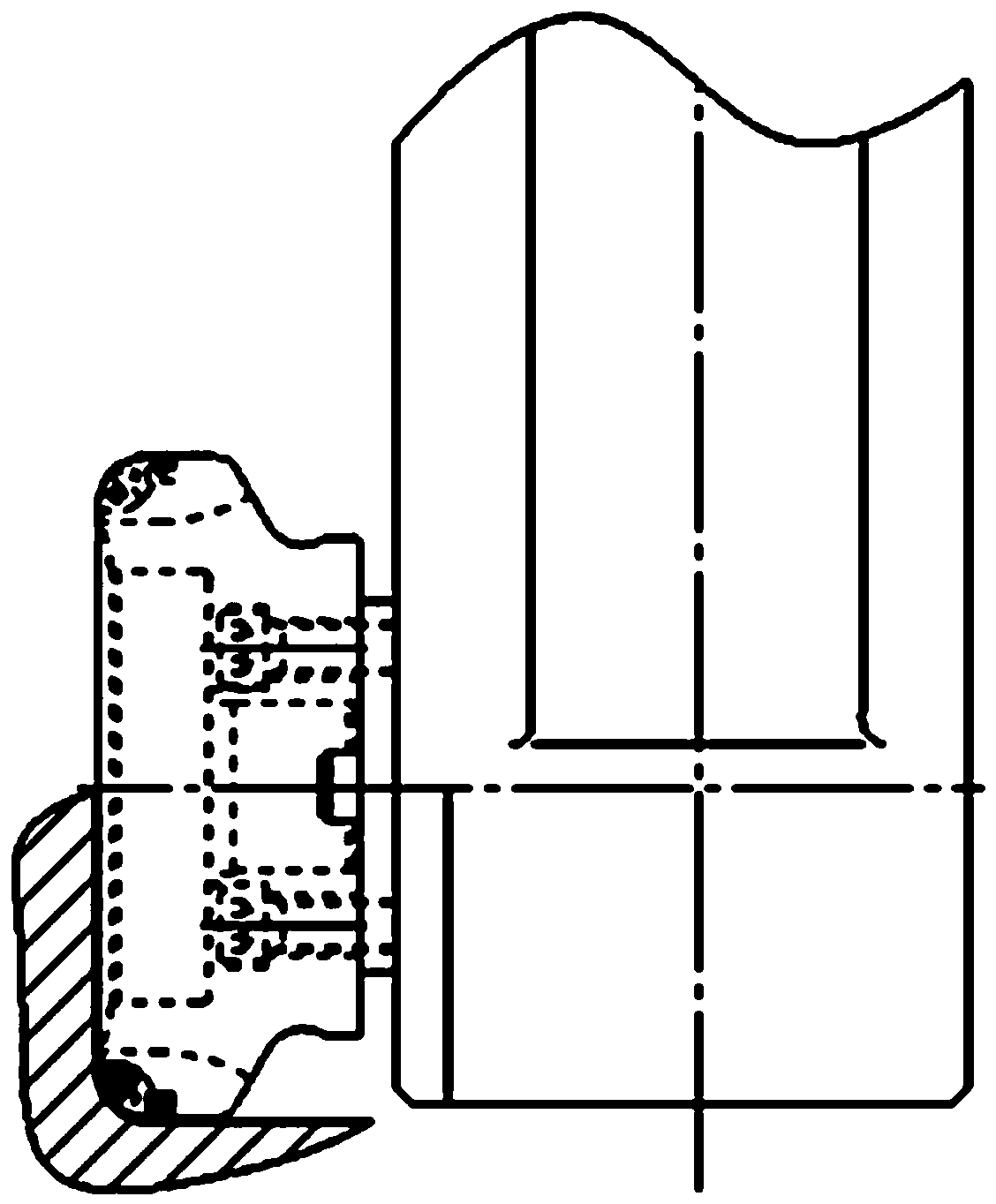
technical field [0001] The invention belongs to a method for processing the hafur surface of a fuselage. Background technique [0002] In the production process of the diesel engine fuselage, there are a series of fuselages (specifications: width × height = 1254 × 1220), the number of cylinders of this type of fuselage is 5 cylinders, 6 cylinders, 8 cylinders, etc., and the length of the fuselage is different. The longest does not exceed 4000mm. The tile cover mounting surface of the crankshaft hole is the key point in the machining of the fuselage. In production, we call it the Hafur surface (the center plane of the crankshaft hole of the fuselage) and the open gear (two parallel planes perpendicular to the center plane of the crankshaft hole, such as figure 1 Dimension 380H7 refers to the surface), and must focus on control (such as figure 1 shown). The width of the half surface of the main engine is generally about 380mm, the thickness is about 80mm, and the distance f...

Claims


Application Information

Patent Timeline
Patent Type & Authority Patents(China)
IPC IPC(8): B23C3/00
Inventor 贠虎臣
Owner 西安陕柴重工核应急装备有限公司
Learn More