Elastic clamp applied to thin sheet parts of laser micromachining machine tool

A machine tool and laser technology, applied in manufacturing tools, laser welding equipment, metal processing equipment, etc., can solve the problems of unreliable positioning, time-consuming clamping, poor versatility, etc., and achieve the effect of low cost, simple structure, and convenient adjustment

Inactive Publication Date: 2016-02-10
HUAIYIN INSTITUTE OF TECHNOLOGY
View PDF7 Cites 6 Cited by
  • Summary
  • Abstract
  • Description
  • Claims
  • Application Information

AI Technical Summary

Problems solved by technology

[0003] At present, the positioning and clamping of thin sheet parts of laser micromachining machine tools is usually carried out with adhesive tape. The negative pressure generated by the flow forms an adsorption force on the parts, but the corresponding processing parts of the parts on the fixture need to be processed to accommodate waste materials. Therefore, with the different sizes of parts and different processing positions, the fixtures must be changed accordingly. This kind of fixture is universal. Relatively poor

Method used


Image

  • Elastic clamp applied to thin sheet parts of laser micromachining machine tool
  • Elastic clamp applied to thin sheet parts of laser micromachining machine tool
  • Elastic clamp applied to thin sheet parts of laser micromachining machine tool

Examples


Embodiment Construction

[0034] The technical solution of the present invention will be further described below in conjunction with the accompanying drawings, but it should not be construed as a limitation on the technical solution.

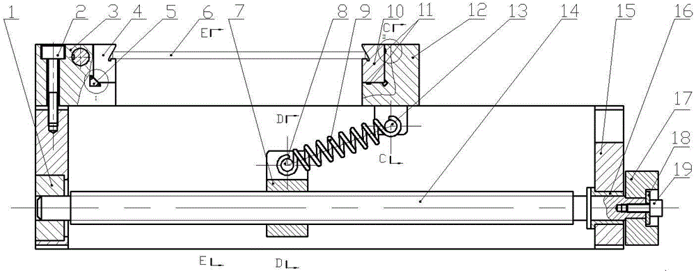
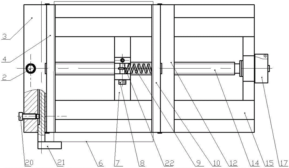
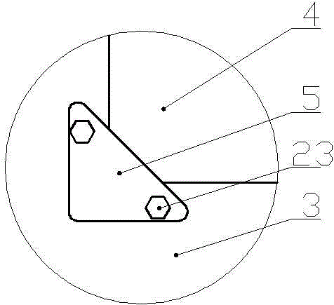
[0035] Such as Figure 1-7 As shown, the fixture includes a clamp body 15, a fixed clamp base 3, a movable clamp base 12, No. 1 quick-change jaw 4, No. 2 quick-change jaw 10 and a screw rod 14. There is a dovetail above the clamp body 15, and the clamp body The middle of 15 is a through groove, the nut 7 is threadedly connected in the middle of the screw mandrel 14, the screw mandrel 14 passes through the through groove of the clamp body 15, the left end of the screw rod 14 is inserted into the left end hole of the clamp body 15 and is connected with the No. 1 shaft sleeve 1 To form a small clearance fit, the right end of the screw rod 14 is inserted into the right end hole of the clamp body 15 and forms a small interference fit with the No. 2 bushing 16, and the knob 17...


PUM


Abstract

The invention discloses an elastic clamp applied to thin sheet parts of a laser micromachining machine tool. The clamp comprises a clamp body (15), a fixed clamp base (3), a movable clamp base (12) and a screw rod (14), wherein a nut (7) is connected to the middle of the screw rod (14); the screw rod (14) penetrates through a through groove of the clamp body (15); the left end of the screw rod (14) is inserted into a left end hole of the clamp body (15); the right end of the screw rod (14) is inserted into a right end hole of the clamp body (15); a rotary knob (17) is fixed to the right end of the screw rod (14); the nut (7) is clamped in the through groove in the middle of the clamp body (15); the fixed clamp base (3) is fixed to the clamp body (15); a dovetail groove under the movable clamp base (12) is connected to a dovetail at the upper part of the clamp body (15); the movable clamp base (12) is connected to the nut (7) through a spring I (9). The elastic clamp is simple in structure, convenient to adjust, low in cost and wide in adjusting range, and has good generality.

Description

technical field [0001] The invention relates to a clamp, in particular to an elastic clamp for sheet parts of a laser micromachining machine tool. Background technique [0002] Laser micromachining machine tools use the laser beam to focus the spot to etch the parts, directly scan and write micrographics on the base material, or process three-dimensional microstructures, or perform microhole processing. Laser micromachining machine tools are currently mainly used in the surface microstructure processing of thin slice parts, such as silicon wafers, ceramic wafers, etc. These materials are mostly brittle materials with thin thickness, and a slightly larger clamping force will break the material, so for brittle The positioning and clamping of large thin sheet parts on the laser micromachining machine becomes a problem. [0003] At present, the positioning and clamping of thin sheet parts of laser micromachining machine tools is usually carried out with adhesive tape. The nega...

Claims


Application Information

Patent Timeline
Patent Type & Authority Applications(China)
IPC IPC(8): B23K26/70B23K37/04B23K26/362
CPCB23K37/0408
Inventor 陈前亮颜彬裴旭许兆美蒋素琴畅皓皓李伯奎王玲
Owner HUAIYIN INSTITUTE OF TECHNOLOGY
Why Eureka
Try Eureka