CO conversion reaction furnace

A technology of transformation reaction and furnace body, applied in the direction of inorganic chemistry, non-metallic elements, chemical instruments and methods, etc., to achieve the effect of avoiding side reactions of methanation

Active Publication Date: 2016-02-10
CHINA PETROLEUM & CHEM CORP
View PDF5 Cites 2 Cited by
  • Summary
  • Abstract
  • Description
  • Claims
  • Application Information

AI Technical Summary

Problems solved by technology

[0006] The technical scheme of the process involved in patent CN201210215513 is that before the process gas enters the converter furnace, it first passes through a cooling device and a temperature raising device, and adjusts its temperature before entering 1# without affecting the water-gas ratio of the process gas. The main conversion furnace, so as to adjust the bed temperature of the main conversion system, the patent does not exchange heat inside the conversion furnace

Method used


Image

  • CO conversion reaction furnace

Examples


Embodiment 1

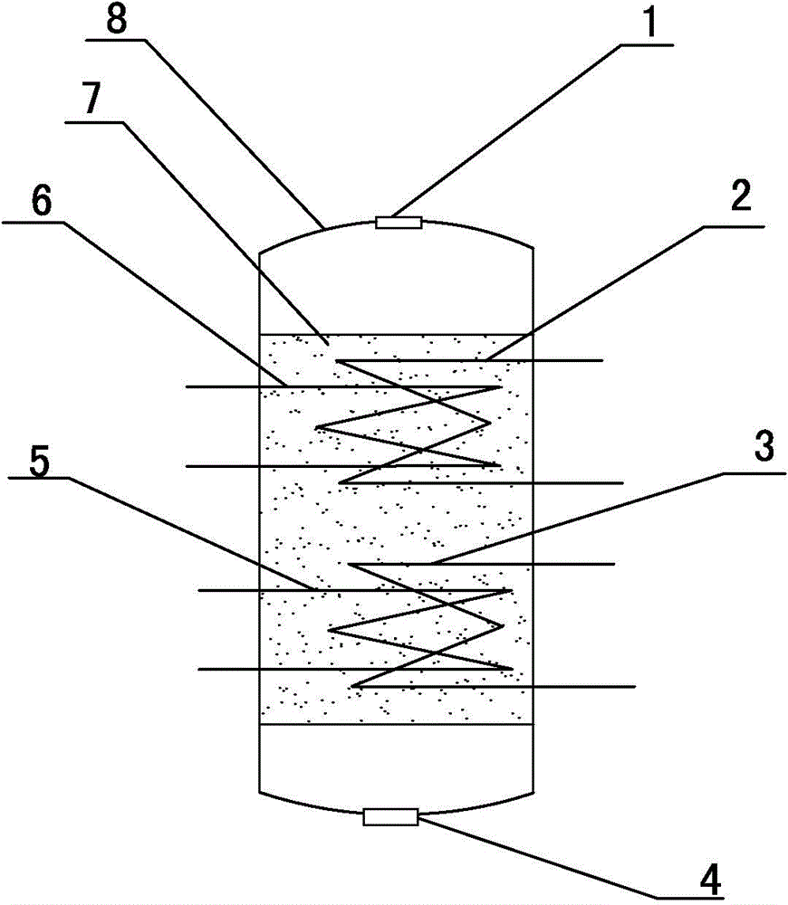
[0019] Such as figure 1 As shown, including the body of furnace 8, the top of the body of furnace 8 is provided with a feed inlet 1, the bottom of the body of furnace 8 is provided with a discharge port 4, the inside of the body of furnace 8 is provided with a catalyst bed 7, and the distance from the top of the body of furnace 8 is 100% of that of the body of furnace. The first heat exchange device is set at 16% of the height of the furnace body 8. The first heat exchange device is composed of the first large heat exchange coil 2 and the first small heat exchange coil 6. Set up the second heat exchange device at 20%, the second heat exchange device is composed of the second large heat exchange coil 3 and the second small heat exchange coil 4, the first large heat exchange coil 2 and the second large heat exchange coil The pipe 3 diameter is 75% of the furnace body diameter, and the diameter of the first small heat exchange coil 6 and the second small heat exchange coil 5 is 5...

Embodiment 2

[0021] Such as figure 1 As shown, including the body of furnace 8, the top of the body of furnace 8 is provided with a feed inlet 1, the bottom of the body of furnace 8 is provided with a discharge port 4, the inside of the body of furnace 8 is provided with a catalyst bed 7, and the distance from the top of the body of furnace 8 is 100% of that of the body of furnace. The first heat exchange device is set at 22% of the height of the furnace body. The first heat exchange device is composed of the first large heat exchange coil 2 and the first small heat exchange coil 6. The distance from the bottom of the furnace body 8 accounts for 20% of the height of the furnace body The second heat exchange device is set at 25%, the second heat exchange device is composed of the second large heat exchange coil 3 and the second small heat exchange coil 4, the first large heat exchange coil 2 and the second large heat exchange coil The pipe 3 diameter is 65% of the furnace body diameter, and...


PUM


Abstract

The invention belongs to the technical field of CO sulfur resistant conversion, and specifically relates to a CO conversion reaction furnace. The furnace comprises a furnace body, a catalyst bed is arranged in the furnace body; a first heat exchange device is arranged on a position (A), the distance between the top of the furnace and the position (A) accounts for 16 to 22% of the height of the furnace, the first heat exchange device is composed of a first large heat exchange coil pipe and a first small heat exchange coil pipe; a second heat exchange device is arranged on a position (B), the distance between the bottom of the furnace and the position (B) accounts for 20 to 25% of the height of the furnace, the second heat exchange device is composed of a second large heat exchange coil pipe and a second small heat exchange coil pipe; the diameters of the first large heat exchange coil pipe and the second large heat exchange coil pipe is 75 to 55% of the diameter of the furnace body, and the diameters of the first small heat exchange coil pipe and the second small heat exchange coil pipe is 45 to 55% of the diameter of the catalyst bed. The temperature of the bed is effectively controlled in a range of 320 to 380 DEG C so as to avoid the methanation by-reactions; at the same time the reaction speed is taken into account, a section of conversion can be effectively arranged to meet the requirements on CO content, and the CO conversion reaction furnace is suitable for technology with different water / gas ratios and CO contents.

Description

technical field [0001] The invention belongs to the technical field of CO sulfur-resistant conversion, and in particular relates to a CO conversion reaction furnace. Background technique [0002] In the field of CO sulfur tolerance conversion, common reactor types include adiabatic reactor and isothermal reactor. The bed temperature of the adiabatic reaction furnace increases gradually from the inlet to the bottom, and the temperature of the hot spot at the bottom is determined by the depth of reaction. The factors affecting the depth of reaction include water-gas ratio, CO content, temperature, high water-gas ratio, high CO content, The lower the layer temperature, the deeper the reaction depth. The CO shift reaction is an exothermic reaction, the reaction depth is large, the hot spot temperature of the bed is high, and the adiabatic reaction furnace will inevitably appear overheating, which will have a negative impact on the life of the catalyst and equipment, and the hig...

Claims


Application Information

Patent Timeline
Patent Type & Authority Applications(China)
IPC IPC(8): C01B3/16
Inventor 齐焕东白志敏赵庆鲁王昊姜建波薛红霞
Owner CHINA PETROLEUM & CHEM CORP
Why Eureka
Try Eureka