
Underground visual probing equipment and method

A kind of equipment and downhole pipe string technology, applied in the field of downhole visual detection equipment, can solve the problems of high transparency requirements, inability to adapt to high temperature in deep wells, poor temperature resistance of cameras and power supplies, etc.

Inactive Publication Date: 2016-02-10
中石化石油工程技术服务有限公司 +1
View PDF20 Cites 19 Cited by
  • Summary
  • Abstract
  • Description
  • Claims
  • Application Information

AI Technical Summary

Problems solved by technology

The existing downhole visual detection equipment mainly uses cables or optical fibers to run into the well to detect the vertical well section. In addition, the existing downhole visual detection equipment has high requirements on the transparency of the liquid in the wellbore. At the same time, the existing downhole visual detection equipment It is also impossible to complete the detection of directional wells and horizontal wells
In addition, the camera and power supply have poor temperature resistance and cannot adapt to the high temperature of deep wells

Method used


Image

  • Underground visual probing equipment and method
  • Underground visual probing equipment and method
  • Underground visual probing equipment and method

Examples


Embodiment Construction

[0026] It should be understood that the specific embodiments described here are only used to explain the present invention, not to limit the present invention.

[0027] It should be noted that, in the description of the present invention, the terms "horizontal", "vertical", "upper", "lower", "front", "rear", "left", "right", "vertical", The orientation or positional relationship indicated by "horizontal", "top", "bottom", "inner", "outer", etc. is based on the orientation or positional relationship shown in the drawings, and is only for the convenience of describing the present invention and simplifying the description, and It is not to indicate or imply that the device or element referred to must have a particular orientation, be constructed in a particular orientation, or operate in a particular orientation, and thus should not be construed as limiting the invention.

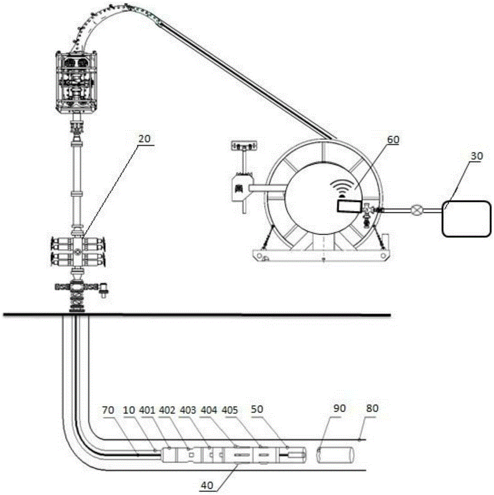
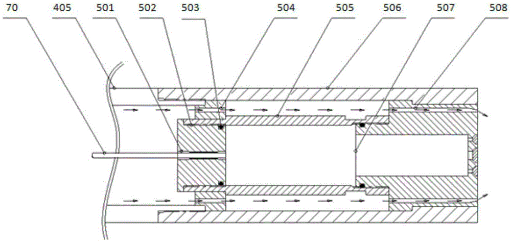
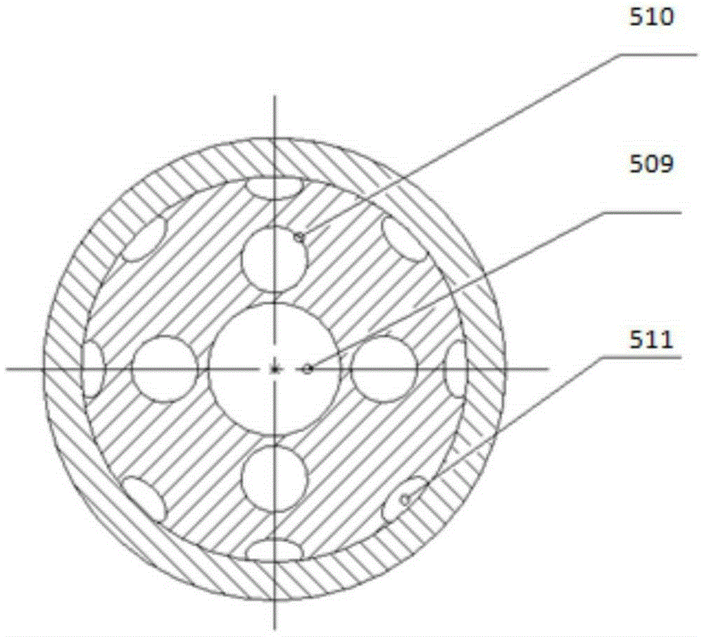
[0028] refer to figure 1 and figure 2 , figure 1 It is an overall schematic diagram of a preferred embo...


PUM


Abstract

The invention provides underground visual probing equipment which comprises a ground pump injection system, a coiled tubing device, a coiled tubing blowout preventing device, a rotating communication device, an underground tubular column string and a cable. The lower portion of the underground tubular column string is connected with a camera supporting barrel, a camera, an overflowing channel and a water spraying hole are arranged in the camera supporting barrel, one end of the overflowing channel is communicated with the coiled tubing, the other end of the overflowing channel is communicated with the water spraying hole, and the cable is arranged in the coiled tubing to connect the camera with the rotating communication device. The invention further provides an underground visual probing method. The underground visual probing equipment can complete whole detection for a directional well and a horizontal well, and can obtain clear image data in the complex environment of turbid liquid and high underground temperature in a well shaft.

Description

technical field [0001] The invention relates to the technical field of petroleum industry detection, in particular to a downhole visual detection device and a downhole visual detection method. Background technique [0002] During the construction of oil and gas wells, downhole visual detection equipment is mainly used for salvage, tubing and casing inspection, mechanical problem inspection, fluid inlet identification, open hole logging and perforation hole fluid detection, etc. Downhole visual inspection is a new technology developed in recent years to solve complex well conditions in oilfields. This technology provides a strong basis for oil and gas well construction with remarkable effects and has a broad market at home and abroad. [0003] In the past, methods such as well temperature logging, fluid resistance logging, rotameter measurement, cork pushing, and packer pressure testing were often used to check the location and condition of casing leakage, but the shape and o...

Claims


Application Information

Patent Timeline
IPC IPC(8): E21B47/002E21B47/017E21B23/00
Inventor 袁发勇张国锋高云伟孙文常何龙姜远福陈龙江强褚晓丹赵勇
Owner 中石化石油工程技术服务有限公司
Learn More