Drilling machine system based on sliding guide drilling closed loop control and drilling method

A sliding-steering, closed-loop control technology, applied in the automatic control system of drilling, directional drilling, drilling equipment, etc., can solve the problems that affect the drilling progress and increase the drilling cost, so as to improve the quality of the wellbore, improve the operation efficiency and control accuracy Effect

Active Publication Date: 2015-11-11
CHINA NAT OFFSHORE OIL CORP +1
View PDF10 Cites 19 Cited by
  • Summary
  • Abstract
  • Description
  • Claims
  • Application Information

AI Technical Summary

Problems solved by technology

Obviously, this way of swinging the tool face relying on the experience of

Method used


Image

  • Drilling machine system based on sliding guide drilling closed loop control and drilling method
  • Drilling machine system based on sliding guide drilling closed loop control and drilling method
  • Drilling machine system based on sliding guide drilling closed loop control and drilling method

Examples


Embodiment Construction

[0019] The present invention will be described in detail below in conjunction with the accompanying drawings and embodiments.

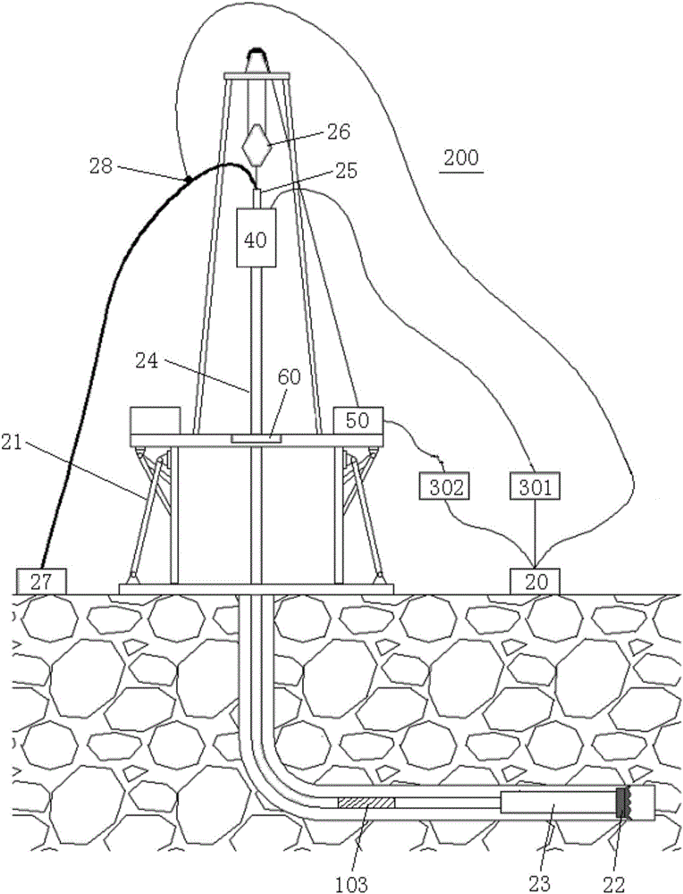
[0020] like figure 1 , figure 2 As shown, the drilling rig system of the present invention includes a sliding steerable drilling closed-loop control system 100 and a steerable drilling system 200 .

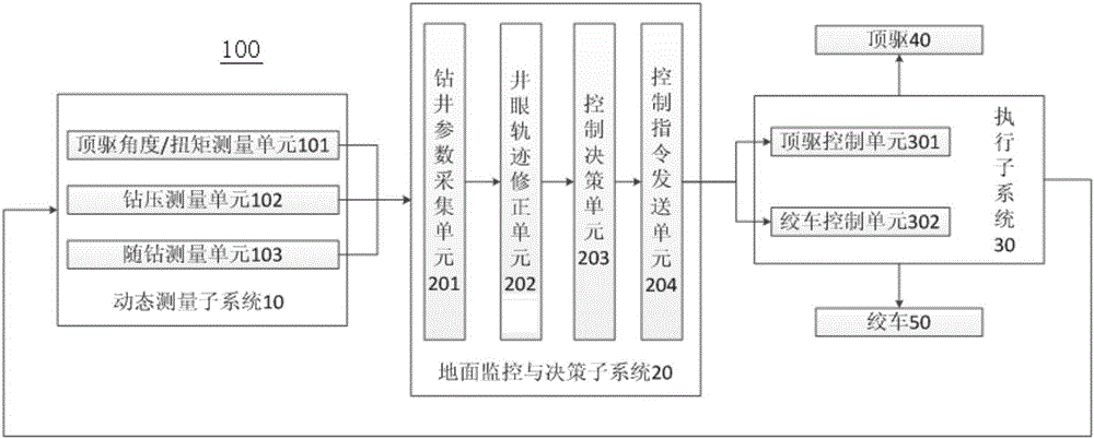
[0021] like figure 2 As shown, the sliding steerable drilling closed-loop control system 100 of the present invention includes a dynamic measurement subsystem 10 , a ground monitoring and decision-making subsystem 20 and an execution subsystem 30 .

[0022] Wherein, the dynamic measurement unit subsystem 10 includes a top drive angle / torque measurement unit 101 for measuring the rotation angle or torque of the top drive, a weight-on-bit measurement unit 102 for measuring the weight-on-bit / torque near the drill bit, and a The measurement-while-drilling unit 103 for measuring actual drilling trajectory parameters such as well deviation and azimuth, and...


PUM


Abstract

The invention relates to a drilling machine system based on sliding guide drilling closed loop control and a drilling method. The system comprises a dynamic measuring unit sub system, a ground monitoring sub system, an execution sub system and a guide drilling system, wherein the dynamic measuring unit sub system measures the parameters such as the well deviation, the orientation and the tool surface of an underground power drill tool in real time, and sends the parameters to the ground monitoring sub system; the ground monitoring sub system achieves the goal of re-determining the trace of a borehole to be drilled according to the designed borehole track and the target point when the condition that the borehole track deviates the designed borehole track is found through comparison; the ground monitoring sub system determines the top drive/turntable rotating angle and the drilling pressure regulation strategy through being combined with a top drive/turntable-drilling pressure combined control chart obtained according to the many-body dynamics simulation design analysis, and then dynamically regulates the drilling pressure and the drift of the tool surface of the underground power drilling tool through regulating the rotating angle of a top drive/turntable and the speed of a traveling block by the execution sub system, so that the stability of the underground tool surface and the drilling pressure is maintained; the closed loop automatic control of the sliding guide drilling borehole track is realized; the operation efficiency and the control precision of the directional well borehole track are effectively improved; and the borehole quality is improved.

Description

technical field [0001] The invention relates to a drilling rig system and a drilling method, in particular to a drilling rig system and a drilling method based on a sliding-steering drilling closed-loop control. Background technique [0002] Steering screw motor power drilling tools have always had an advantage in directional wells (especially high dogleg) drilling operations. There are two main modes of operation for lead screw motors: rotary mode and directional mode (or guide mode). During drilling in rotary mode, the rotary table or top drive rotates the drill string from the surface at low speed to transmit power to the drill bit, and the motor's elbows point evenly in different directions to drill in a straight line. Due to changes in formation lithology, changes in drilling tool system and drilling engineering parameters, etc., the tool face of downhole dynamic drilling tools is prone to drift, which will cause the actual wellbore trajectory to deviate from the desig...

Claims


Application Information

Patent Timeline
IPC IPC(8): E21B7/04E21B44/00
Inventor 曹砚锋姜伟程载斌周建良何保生李汉兴武广瑷李峰飞
Owner CHINA NAT OFFSHORE OIL CORP
Why Eureka
Try Eureka