A multi-path flow meter calibrating device pulse counting signal reconstruction method

A verification device and pulse counting technology, applied in measurement devices, test/calibration devices, liquid/fluid solid measurement, etc., to prevent false counting of pulses and improve the signal-to-noise ratio

Active Publication Date: 2016-02-10
SOUTH CHINA UNIV OF TECH
View PDF6 Cites 1 Cited by
  • Summary
  • Abstract
  • Description
  • Claims
  • Application Information

AI Technical Summary

Problems solved by technology

[0003] In order to solve the above existing problems and defects, the present invention proposes a method for reconstructing the pulse counting signal of a multi-channel flowmeter verification device, which realizes the method of combining filtering and reconstruct

Method used


Image

  • A multi-path flow meter calibrating device pulse counting signal reconstruction method
  • A multi-path flow meter calibrating device pulse counting signal reconstruction method
  • A multi-path flow meter calibrating device pulse counting signal reconstruction method

Examples


Embodiment Construction

[0016] The present invention will be further described in detail below in conjunction with the embodiments and accompanying drawings.

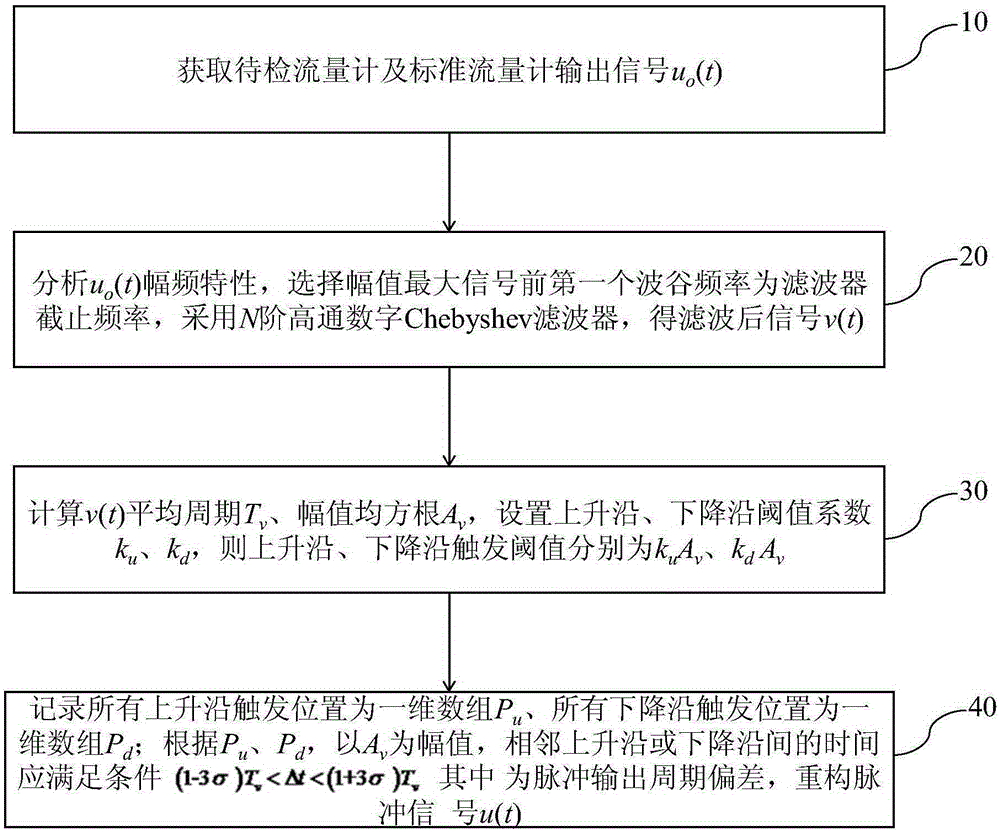
[0017] The present invention removes single-frequency noise based on an N-order high-pass digital Chebyshev filter, and realizes pulse compensation signal reconstruction of a multi-channel flowmeter verification device based on signal reconstruction technology, such as figure 1 As shown, the method includes the following steps:

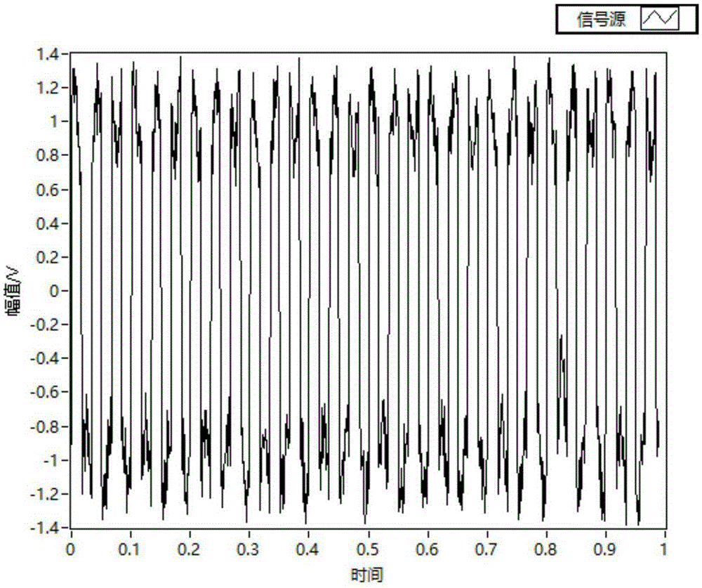
[0018] Step 10. Obtain the output signal u of the flowmeter to be tested and the standard flowmeter o (t), such as figure 2 shown;

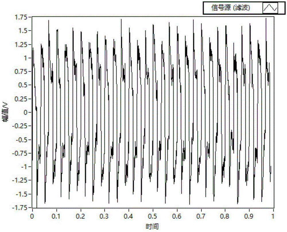
[0019] Step 20, analyze u o (t) Amplitude-frequency characteristics, select the first valley frequency before the maximum amplitude signal as the filter cut-off frequency, and use an N-order high-pass digital Chebyshev filter to obtain the filtered signal v(t);

[0020] Among them, the amplitude square function A(Ω 2 )for:

[0021]

[0022] In the formula, Ω c is the effective...


PUM


Abstract

The invention provides a multi-path flow meter calibrating device pulse counting signal reconstruction method. The method comprises the steps of obtaining output signals uo(t) of to-be-calibrated flow meters and a standard flow meter; analyzing the amplitude-frequency characteristics of the uo(t); selecting the first trough frequency before the signal with the maximum amplitude as the filter cut-off frequency; using an N-order high pass digital Chebyshev filter and obtaining filtered signals v(t); calculating the average period Tv and the amplitude mean square root Av of the v(t); setting the rising edge and falling edge threshold value coefficients ku and kd, the rising edge and falling edge triggering threshold values being kuAv and kdAv; recording all the rising edge triggering positions as a one-dimensional array Pu and all the falling edge triggering positions as a one-dimensional array Pd; reconstructing pulse signals u(t) according to the Pu and Pd and with the Av as the amplitude, the time delta t between adjacent rising edges (falling edges) meeting the condition of (1-3sigma)Tv<delta t<(1+3sigma)Tv, wherein sigma is the pulse output period deviation.

Description

technical field [0001] The invention relates to the field of flowmeter pulse signal denoising, in particular to a pulse counting signal reconstruction method of a multi-channel flowmeter verification device. Background technique [0002] With the development of modern industry, the demand for flowmeters continues to increase, especially the pulse output flowmeter (in the case of a stable flow field, the instantaneous flow rate of the pulse output flowmeter is proportional to the pulse frequency) has been unprecedentedly applied, which is of great significance for its rapid and accurate verification. major. Universal verification device, the industrial computer drives the commutator according to the phase-locked signal of the pulse signal of the flowmeter, and can intercept the pulse signal of the flowmeter for the entire period. However, in multi-position devices, there are non-linear distortions in the signals generated by non-ideal devices such as standard flowmeters, unt...

Claims


Application Information

Patent Timeline
IPC IPC(8): G01F25/00
CPCG01F25/00
Inventor 刘桂雄黄坚
Owner SOUTH CHINA UNIV OF TECH
Why Eureka
Try Eureka