Parallel power conversion control device

A technology of power conversion and control device, applied in the direction of regulating electric variables, control/regulating systems, instruments, etc., can solve problems such as affecting the tracking effect of the inverter, and achieve the effect of overcoming the poor effect of circulating current suppression

Active Publication Date: 2016-02-10
SHANGHAI MITSUBISHI ELEVATOR CO LTD
View PDF3 Cites 3 Cited by
  • Summary
  • Abstract
  • Description
  • Claims
  • Application Information

AI Technical Summary

Problems solved by technology

However, the independent current tracking method is to set the current command value of each inverter as n (n ≥ 2, the number of inverters) equal division of the total expected current, and make the actual current of each inverter track its actual current through control. The current command value can be used to achieve the two control objectives of the parallel power conversion system at the same time - the tracking of the total output current of all inverters to the

Method used


Image

  • Parallel power conversion control device
  • Parallel power conversion control device
  • Parallel power conversion control device

Examples


Embodiment 1

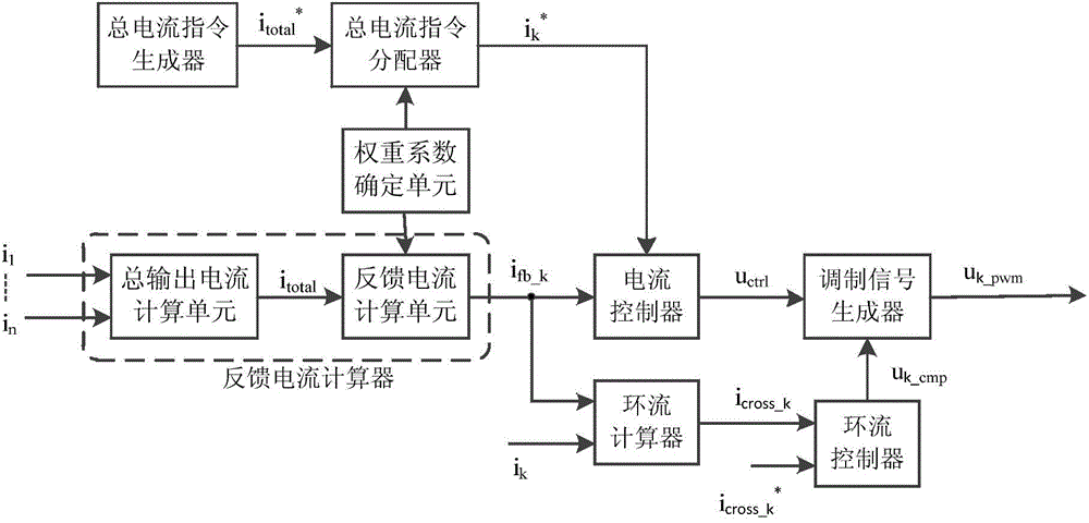
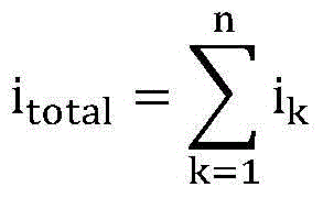
[0038] The structure of the parallel power conversion control device used in the parallel power conversion system composed of at least two power converters connected in parallel in the present invention is as follows: figure 1 As shown, it is mainly composed of a total current command generator, a weight coefficient determination unit, a total current command distributor, a current controller, a circulating current calculator, a circulating current controller, a modulation signal generator, and a feedback current calculator. The total current command generator is used to generate the total current command value that should be output by the parallel power conversion system; the weight coefficient determination unit is used to determine the proportion of the current of each power converter in the total output current of the parallel power conversion system, output Corresponding to the weight coefficient of the power converter; the total current command distributor is used to dist...

Embodiment 2

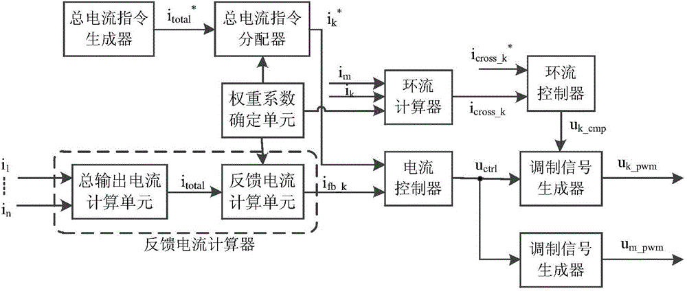
[0058] like figure 2 As shown, this embodiment is similar to Embodiment 1, and only the differences from Embodiment 1 will be described below.

[0059] In this embodiment, the parallel power conversion control device first selects the mth power converter as the reference power converter. For the control of any other non-reference power converter (such as the power converter numbered k, k≠m), the corresponding circulating current calculator calculates the circulating current of the kth power converter according to the following formula, i corss_k :

[0060] i corss_k = i k -(α k / α m )×i m Formula 5

[0061] Among them, i corss_k is the circulating current of the kth power converter, i k and i m are the current values ​​of the kth and m power converters respectively, i fb_k is the current feedback value of the kth power converter, α k and alpha m are the weight coefficients of the kth and m power converters respectively, and m is the serial number of the reference...


PUM


Abstract

The invention discloses a parallel power conversion control device which comprises a total current instruction generator, a weight coefficient determination unit, a total current instruction distributor, a feed current calculator, a current controller, a circular current calculator, a circular current controller and a modulating signal generator, wherein the circular current calculator is used for calculating circular current of a corresponding power converter according to an output current value of the power converter; the circular current controller is used for controlling circular current of the power converter according to the calculation result of the circular current calculator and outputting a circular current compensation voltage signal; the modulating signal generator is used for generating a modulating signal required by a PWM (Pulse-Width Modulation) unit to carry out pulse wide modulation according to a control voltage signal outputted by the current controller and the circular current compensation voltage signal outputted by the circular current controller. According to the parallel power conversion control device disclosed by the invention, tracking performance and circular current inhibiting effect of total output current on a total current instruction value can be effectively improved, and the calculation load of a microprocessor is effectively reduced.

Description

technical field [0001] The invention relates to the control field of power conversion devices, in particular to a parallel power conversion control device for a parallel power conversion system composed of at least two power converters connected in parallel. Background technique [0002] The parallel connection of power conversion devices is an important technical means to expand the power of power conversion devices, improve reliability, and realize flexible power adjustment of power conversion devices. Document 1 (multi-inverter parallel control technology for motor drive system, Journal of Electric Machine and Control, 2010, 14(2): 36-40, 46) proposes to independently control each inverter to make its current track its expected value , so as to realize the tracking of the total current of each inverter to its command value (subsequently referred to as the independent current tracking method). Although it sets the current command value of each inverter as an equal divisio...

Claims


Application Information

Patent Timeline
IPC IPC(8): G05F3/26
Inventor 陈玉东
Owner SHANGHAI MITSUBISHI ELEVATOR CO LTD
Why Eureka
Try Eureka