
Method for realizing MAX 2769 interface control by adopting universal digital I/O

A MAX2769, interface control technology, applied in the field of electronic measurement, can solve the problems of complicated software programming and long hardware production and development cycle, etc., and achieve the effect of intuitive and simple and reliable hardware connection, simple design, and wide selection of devices.

Inactive Publication Date: 2016-02-10
陈钦碧
View PDF3 Cites 3 Cited by
  • Summary
  • Abstract
  • Description
  • Claims
  • Application Information

AI Technical Summary

Problems solved by technology

The control of its internal state needs to be configured through a dedicated three-wire serial port circuit, which includes setting its gain, bandwidth, signal branch and other working parameters; usually it is necessary to design a dedicated interface circuit using FPGA, CPLD and other technologies, and it is also necessary to use a crystal oscillator To realize the clock signal, the hardware production and development cycle is long, and the software compilation is complicated

Method used


Image

  • Method for realizing MAX 2769 interface control by adopting universal digital I/O
  • Method for realizing MAX 2769 interface control by adopting universal digital I/O
  • Method for realizing MAX 2769 interface control by adopting universal digital I/O

Examples


Embodiment 1

[0022] The computer controls MAX2769A through USB9812C, and its hardware interface is as follows: figure 1 As shown in the figure, AC represents the zero live wire connected to the AC power, and FG represents the ground wire connected to the AC power. The corresponding relationship between the general I / O and the parallel port MAX2769A port is shown in the table below. This design mainly considers the control signal and the grounding path to realize Basic control functions.

[0023] Port Correspondence

[0024]

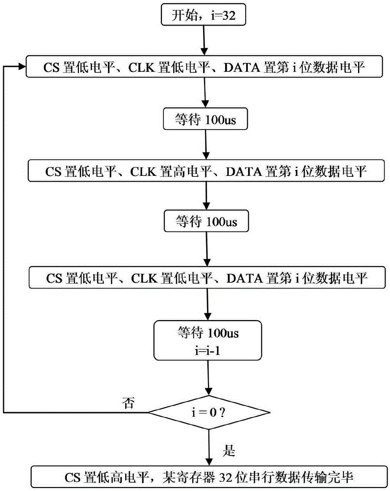
[0025] according to figure 1 connection, the I / O output level of the USB9812C can directly control the chip select (CS), data (DATA), clock (SCLK), idle (IDLE) and Shutdown (SHDN) pin. According to a certain timing, control the I / O output TTL level of USB9812C, send control signals and required data to MAX2769, and then the purpose of changing the working state of MAX2769 can be achieved.

[0026] 1. MAX2769A chip SPI timing requirements

[0027] The MAX2769A ...


PUM


Abstract

The present invention belongs to the technical field of realizing interface control by using a universal digital I / O, and relates to a method for realizing MAX 2769 interface control by adopting a universal digital I / O. The method comprises following steps that functions of output pins of the universal digital I / O are planned and the output pins are connected with MAX 2769 serial interface terminals; and according to an MAX 2769 serial interface timing sequence and a serial-parallel data conversion requirement, interface control is carried out by serial data transmission. According to the method provided by the present invention, the range of optional devices of the universal I / O is wide; the hardware connection is directly visible, simple and reliable; the problems of complex design and long production implementation cycle of FPGA and CPLD circuits are avoided; SPI control word sending is achieved by an inexact but synchronous timing relationship to meet a control requirement; control functions which usually can only be implemented by using FPGA and CPLD are provided; and the method is simple in design and economical in implementation, and can be used for a variety of chip controls which need an SPI interface for status setting.

Description

technical field [0001] The invention belongs to the technical field of electronic measurement, and relates to a method for realizing MAX2769 interface control by using a general digital I / O. Background technique [0002] MAX2769 is a navigation star signal receiving chip produced by MAXIM, which is widely used in the reception, measurement and positioning of GPS, GLONASS and Galileo navigation star signals. Its functions include radio frequency amplification, intermediate frequency conversion, sampling output of up to three digits, etc. The control of its internal state needs to be configured through a dedicated three-wire serial port circuit, which includes setting its gain, bandwidth, signal branch and other working parameters; usually it is necessary to design a dedicated interface circuit using FPGA, CPLD and other technologies, and it is also necessary to use a crystal oscillator To realize the clock signal, the hardware production and development cycle is long, and th...

Claims


Application Information

Patent Timeline
Patent Type & Authority Applications(China)
IPC IPC(8): G06F13/42G06F13/20
CPCG06F13/4282G06F13/20
Inventor 陈钦碧张俊华何文兵赵天宫胡大治唐娟李永志
Owner 陈钦碧
Learn More