
Overvoltage protection circuit, overvoltage protection method and gate driving integrated circuit

A technology for protecting circuits and integrated circuits. It is applied in the field of overvoltage protection circuits and gate drive integrated circuits. It can solve problems such as load damage and achieve the effect of simple structure.

Active Publication Date: 2016-02-10
UPI SEMICON CORP
View PDF6 Cites 0 Cited by
  • Summary
  • Abstract
  • Description
  • Claims
  • Application Information

AI Technical Summary

Problems solved by technology

The load can therefore be damaged by high voltage stress

Method used


Image

  • Overvoltage protection circuit, overvoltage protection method and gate driving integrated circuit
  • Overvoltage protection circuit, overvoltage protection method and gate driving integrated circuit
  • Overvoltage protection circuit, overvoltage protection method and gate driving integrated circuit

Examples


Embodiment Construction

[0070] Reference will now be made in detail to exemplary embodiments of the present invention, and examples of the exemplary embodiments are illustrated in the accompanying drawings. In addition, elements / components with the same or similar numbers used in the drawings and the embodiments are used to represent the same or similar parts.

[0071] In the following embodiments, when an element is referred to as being “connected” or “coupled” to another element, it may be directly connected or coupled to another element, or there may be intervening elements. The term "circuit" or "unit" may refer to at least one element or multiple elements, or active and / or passive elements coupled together to provide suitable functions. The term "signal" can be expressed as at least one current, voltage, load, temperature, data or other signal.

[0072] Reference will now be made in detail to the embodiments of the present invention, and examples of the embodiments are illustrated in the accompanyin...


PUM


Abstract

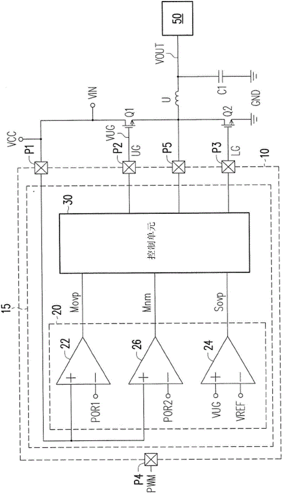
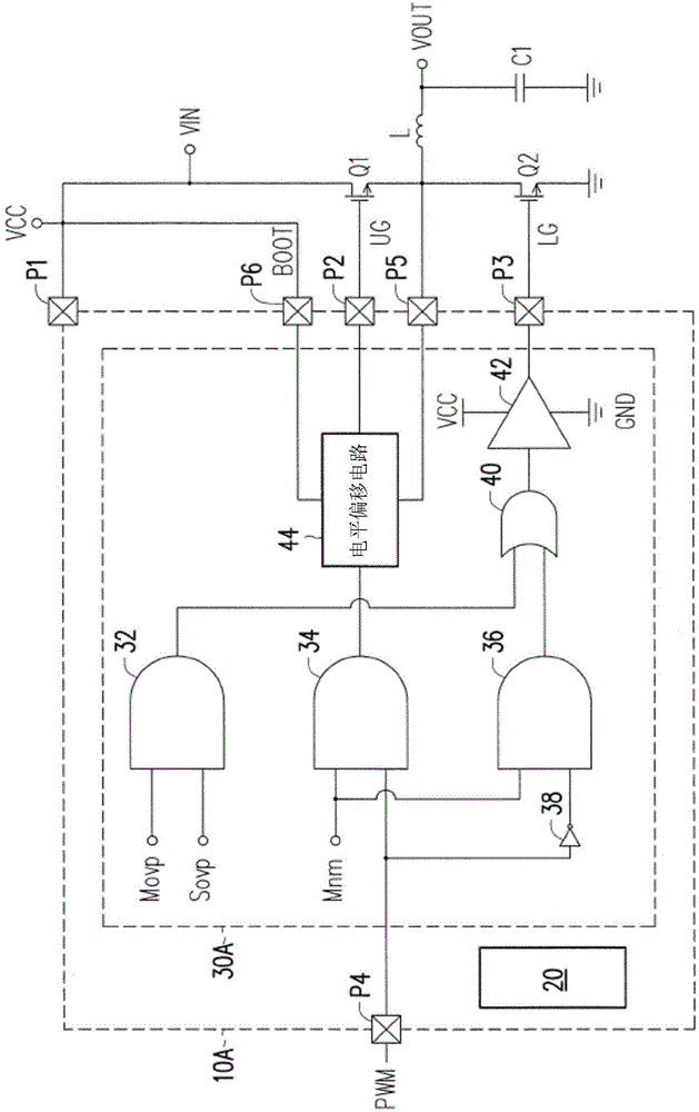
The present invention provides an overvoltage protection circuit, an overvoltage protection method and a gate driving integrated circuit. The overvoltage protection method is used for the overvoltage protection circuit. The overvoltage protection circuit is coupled to a first switch which has a control end. The overvoltage protection method comprises the following steps: comparing a first voltage preset value with an operating voltage to generate a first enable signal; and comparing a voltage of the control end of the first switch with a reference voltage when the first enable signal is generated, so as to determine whether the overvoltage protection circuit executes an overvoltage protection operation, thereby avoiding damages to a load caused by high voltage stress.

Description

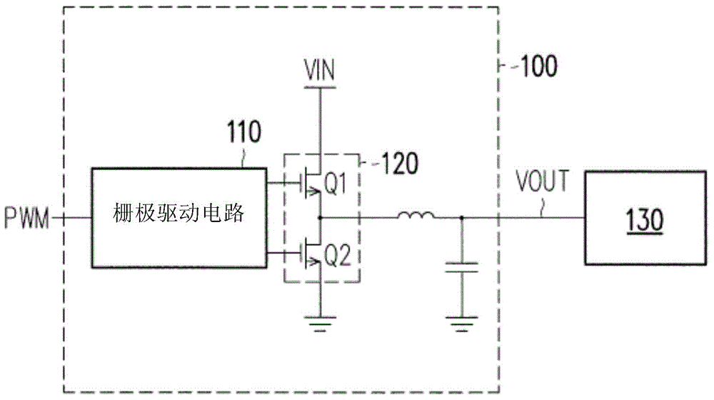
Technical field [0001] The invention relates to an overvoltage protection technology, in particular to an overvoltage protection circuit, an overvoltage protection method and a gate drive integrated circuit. Background technique [0002] figure 1 It is a schematic diagram of the application of the existing power conversion circuit. The power conversion circuit 100 includes a gate driving circuit 110 and an output stage 120. The gate driving circuit 110 performs a switching operation on the first switch Q1 and the second switch Q2 of the output stage 120 according to the pulse width modulation signal PWM, so that the input voltage VIN is converted into the output voltage VOUT and is supplied to the load 130. [0003] The load 130 is a central processing unit or a graphics processing unit, and its power source is the output voltage VOUT. Assuming that the power conversion circuit 100 does not have an overvoltage protection circuit for the output stage 120, the input voltage VIN is ...

Claims


Application Information

Patent Timeline
Patent Type & Authority Applications(China)
IPC IPC(8): H02H3/20H02M1/088
Inventor 徐正青
Owner UPI SEMICON CORP
Learn More