Rotating electric machine

A technology for rotating electrical machines and rotors, applied to synchronous motors with stationary armatures and rotating magnets, electric components, electrical components, etc., can solve the problems of unpredictable permanent magnet temperature, etc., and achieve the goal of suppressing demagnetization and reducing temperature distribution Effect

Active Publication Date: 2016-02-10
MITSUBISHI ELECTRIC CORP
View PDF5 Cites 4 Cited by
  • Summary
  • Abstract
  • Description
  • Claims
  • Application Information

AI Technical Summary

Problems solved by technology

[0008] In addition, when the temperature distribution in the axial direction of the permanent magnet is large, there is also the following problem: Although there is a correlation between the temperature of the permanent magnet and the induced voltage of the motor, the induced voltage can only pass through the permanent magnet under the average temperature. Therefore, if the temperature distribution of the permanent magnets in the axial direction is large, the temperature of each permanent magnet cannot be predicted.

Method used


Image

  • Rotating electric machine
  • Rotating electric machine
  • Rotating electric machine

Examples


Embodiment approach 1

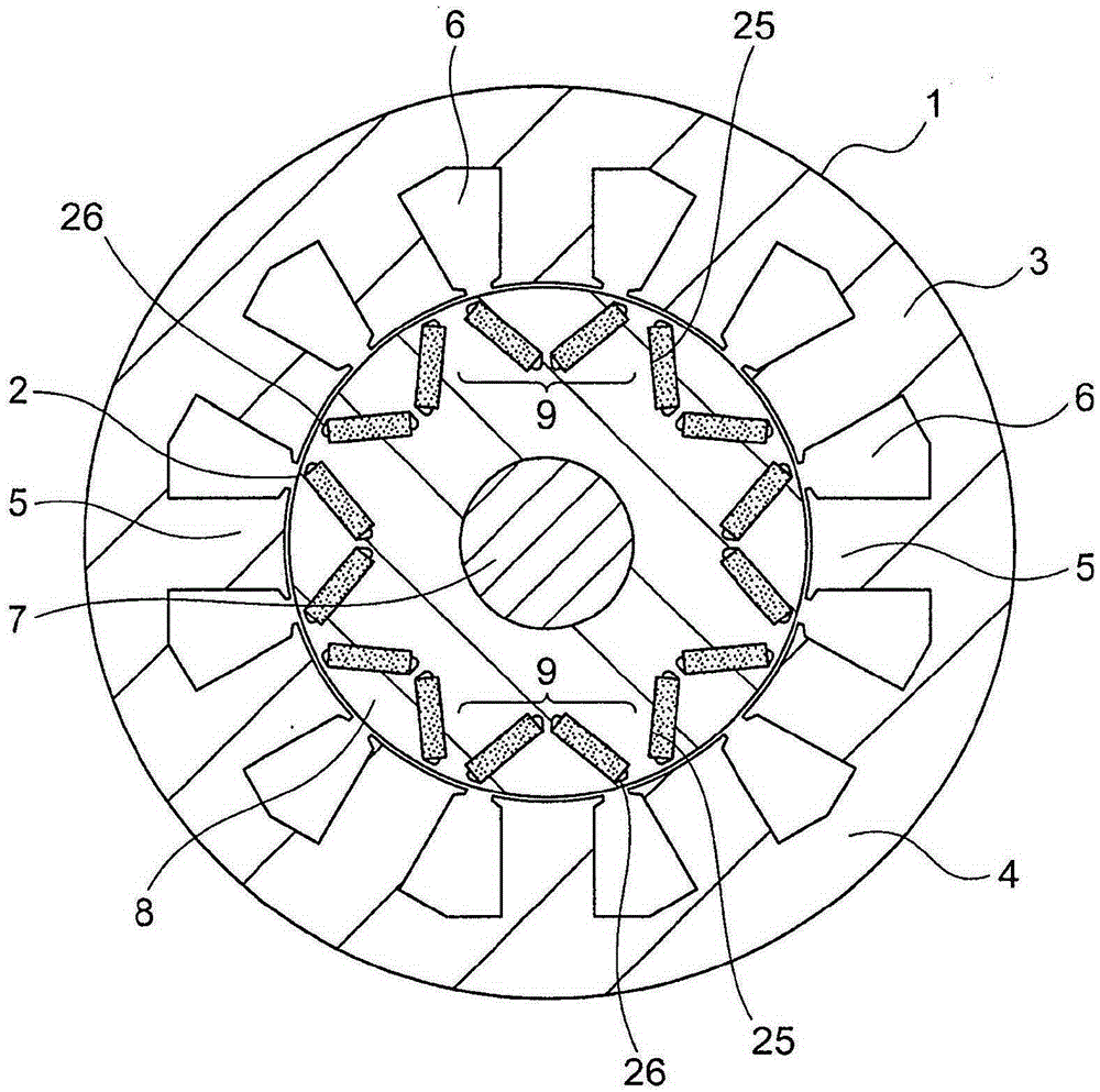
[0032] figure 1 is a front cross-sectional view showing a main part of a motor as a rotating electrical machine according to Embodiment 1 of the present invention, figure 2 yes means figure 1 An enlarged view of the main parts of the motor.

[0033] This motor includes a stator 1 and a rotor 2. The stator 1 has a stator core 3 and stator coils (not shown) wound in slots 6. The stator core 3 has 12 slots 6 through which Teeth 5 extending radially inward from the annular core back 4 are formed at intervals in the circumferential direction, and the rotor 2 is rotatably disposed coaxially with the stator core 3 on the stator. 1 on the inner peripheral side.

[0034] The stator core 3 is formed by laminating thin steel plates.

[0035] The stator coil is composed of three-phase windings (U phase, V phase, W phase) wound on teeth 5. One end of the wire of each phase winding is connected to the converter side, and the other end of the wire is used as a neutral wire to connect wi...

Embodiment approach 2

[0074] Figure 9 It is a front cross-sectional view showing a main part of a motor according to Embodiment 2 of the present invention.

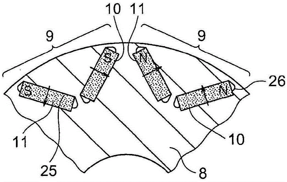
[0075] In this embodiment, the rotor 2 has a rotor core 8 and a plurality of rectangular permanent magnets 18 per pole, and the plurality of permanent magnets 18 are embedded in the rotor core 8 at intervals in the circumferential direction. the outer peripheral side.

[0076] A plurality of magnet housing holes 25 extending in the axial direction and housing the permanent magnets 18 are formed in the rotor core 8 formed by laminating thin steel plates. The permanent magnets 18 housed in the respective magnet housing holes 25 are arranged such that a perpendicular bisector of the permanent magnets 18 passes through the axis of the rotor 2 .

[0077] The permanent magnet 18 has N poles and S poles alternately set along the circumferential direction.

[0078] In addition, gaps 26 are formed at both ends of the magnet housing hole 25 , and th...

Embodiment approach 3

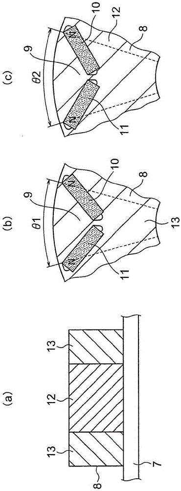
[0094] Figure 13 It is a front cross-sectional view showing a main part of a motor according to Embodiment 3 of the present invention.

[0095] The rotor 2 has: a rotating shaft 7; a rotor core 8 fixed to the rotating shaft 7 by press-fitting, shrink-fitting, or keys; The outer peripheral side of the magnet is composed of three rectangular-shaped first permanent magnets 30 , second permanent magnets 31 and third permanent magnets 32 per pole.

[0096]A plurality of magnet housing holes 25 extending in the axial direction and housing the first permanent magnet 30 , the second permanent magnet 31 and the third permanent magnet 32 ​​are formed in the rotor core 8 formed by laminating thin steel plate layers. The first permanent magnet 30 and the third permanent magnet 32 ​​located on both sides of the second permanent magnet 31 face each other so that the distance between them in the circumferential direction increases in the radially outer direction.

[0097] Such as Figure...


PUM


Abstract

In this motor, a rotor is constituted by a small angle rotor portion and a large angle rotor portion having magnet end-to-end angles different from each other, said magnet end-to-end angles being a plane angle between lines connecting each of the most outer circumferential side end portions of permanent magnets facing each other and the shaft center of the rotor. The rotor is also constituted by stacking, along the shaft line, the small angle rotor portion, the large angle rotor portion, and the small angle rotor portion in this order into three layers. This prevents the permanent magnets from being demagnetized due to temperature rise and also obtains a rotating electric machine having the permanent magnets, the temperature distribution of which is lessened in a shaft line direction.

Description

technical field [0001] The present invention relates to, for example, electric motors for driving electric vehicles and hybrid vehicles, and more particularly, to a rotating electrical machine in which permanent magnets are embedded in the outer peripheral portion of a rotor core. Background technique [0002] Conventionally, an embedded magnet type motor is known in which a rotor core in which two permanent magnets are embedded in a V-shape per pole is composed of first and second split rotor cores split in the axial direction, and the magnetic The circumferential width of the passage forming portion is set to be different in the first and second split rotor cores (for example, refer to Patent Document 1). [0003] prior art literature [0004] patent documents [0005] Patent Document 1: Japanese Patent Laid-Open No. 2006-115584 Contents of the invention [0006] The problem to be solved by the invention [0007] The above-mentioned embedded magnet motor can reduce t...

Claims


Application Information

Patent Timeline
Patent Type & Authority Applications(China)
IPC IPC(8): H02K1/27H02K1/22H02K21/16
CPCH02K29/03H02K1/2766H02K9/10H02K1/06H02K1/16H02K1/276H02K1/32
Inventor 枦山盛幸大谷晃裕
Owner MITSUBISHI ELECTRIC CORP
Why Eureka
Try Eureka