Screw rod installation structure of injection molding machine

A technology for installation structures and injection molding machines, which is applied to mechanical equipment, rigid shaft couplings, couplings, etc., can solve the problems of frequent twisting of the screw, weakening the strength of the screw, and time-consuming and labor-intensive problems, so as to reduce processing and manufacturing cost, eliminate weak links, and improve the effect of screw strength

Active Publication Date: 2016-02-17
DONGHUA MACHINERY
View PDF4 Cites 5 Cited by
  • Summary
  • Abstract
  • Description
  • Claims
  • Application Information

AI Technical Summary

Problems solved by technology

In this structure, a keyway is provided on the screw rod, and a clasp is provided to match the ring groove, which greatly weakens the strength of the screw rod, resulting in frequent occurrence of twisting of the screw rod
However, the clasp ring installation structure has a large number of screws arranged around the circumference, which is time-consuming and labor-intensive in the case of replacing the screw rods.

Method used


Image

  • Screw rod installation structure of injection molding machine
  • Screw rod installation structure of injection molding machine
  • Screw rod installation structure of injection molding machine

Examples


Embodiment 1

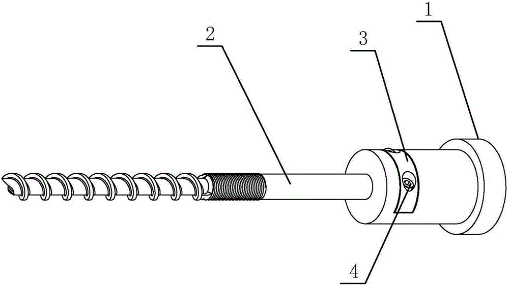
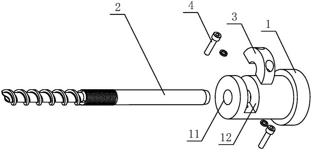
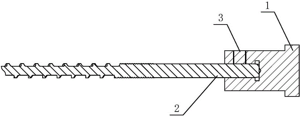
[0032] Embodiment 1: as Figures 1 to 4 As shown, in this embodiment, the snap ring 3 is an independent entity, which is arranged in the rotating shaft 1, and the screw rod 2 is installed and fixed, and is tightly held by the transmission shaft 1 and the snap ring 3, and the side of the rotating shaft 1 is provided with a radial connection The matching groove 12 in the shaft hole 11, the snap ring 3 is put into the matching groove 12, and the bolt 4 is used to tighten the clamping structure so that the clamping structure is tightly attached to the surface of the screw 2, and the torque and axial force are transmitted through compression deformation; For the injection load, it is borne by the inner end surface of the transmission shaft 1.

Embodiment 2

[0033] Embodiment 2: as Figure 5 to Figure 7 As shown, in this embodiment, the end of the rotating shaft 1 is provided with radial separation grooves 13 and axial separation grooves 14 perpendicular to each other, so that the snap ring 3 is separated from the rotating shaft 1 on the side of the connecting shaft hole 11 to form a free end. , The other side part is connected as a whole with the rotating shaft 1, and the free end side of the snap ring 3 is provided with a bolt 4 and is fixedly connected with the rotating shaft 1, so that the inner ring wall of the snap ring 3 radially tightens the screw rod 2. The structure is a semi-separated and tight structure. Also can reach the same effect of embodiment 1.


PUM


Abstract

The invention discloses a screw rod installation structure of an injection molding machine. The screw rod installation structure comprises a rotation shaft and a screw rod. A connection shaft hole is formed in the end of the rotation shaft, and the screw rod is inserted into the connection shaft hole for shaft connection. The rotation shaft is provided with a clamping ring capable of adjusting and hooping the screw rod in the connection shaft hole in the radial direction, and the clamping ring and the rotation shaft are fixedly connected with the screw rod hooped in the radial direction through bolts. According to the screw rod installation structure, the rotation shaft and the clamping ring are used for clasping, the bolts are used for compression, and therefore the clasping structure can be tightly attached to the surface of the screw rod; torque and axial force are transmitted through compression deformation, the stressing weak link of the screw rod is eliminated, and therefore the strength of the screw rod is improved; for disassembling or assembling the screw rod, just the bolts need to be loosened and do not need to the detached, then the screw rod can be disassembled, and therefore frequent replacement of the screw rod is convenient. The screw rod installation structure has the advantages of being simple in structure and convenient to disassemble, assemble and use and lowering the machining and manufacturing cost.

Description

technical field [0001] The invention relates to a screw mounting structure, in particular to a screw mounting structure of an injection molding machine. Background technique [0002] The injection structure of the injection molding machine is the core part of the injection molding machine, and the screw is the core of the core, which plays a decisive role in the molding quality of the product. The melt driver drives the rotating shaft, which drives the screw to rotate and cut the rubber to melt the glue; the injection driver drives the injection seat, which is transmitted to the screw through the rotating shaft to perform the forward or backward injection and pumping action. In the process of melting glue and injecting glue, the screw will always fail to varying degrees. On the other hand, with the frequent replacement of screw rods for mold replacement, easy disassembly and assembly of the screw rods has become a necessary condition for designing screw rod installation and...

Claims


Application Information

Patent Timeline
Patent Type & Authority Applications(China)
IPC IPC(8): B29C45/17
CPCF16D1/0864B29C45/1775
Inventor 刘洋孟倞黄伦兵黄卓亮
Owner DONGHUA MACHINERY
Why Eureka
Try Eureka