Glass conveying device
A conveying device, glass technology, applied in the direction of conveyor objects, transportation and packaging, loading/unloading, etc., can solve problems such as personal injury, glass damage, and reduced conveying efficiency
- Summary
- Abstract
- Description
- Claims
- Application Information
AI Technical Summary
Problems solved by technology
Method used
Image

Examples
Embodiment Construction
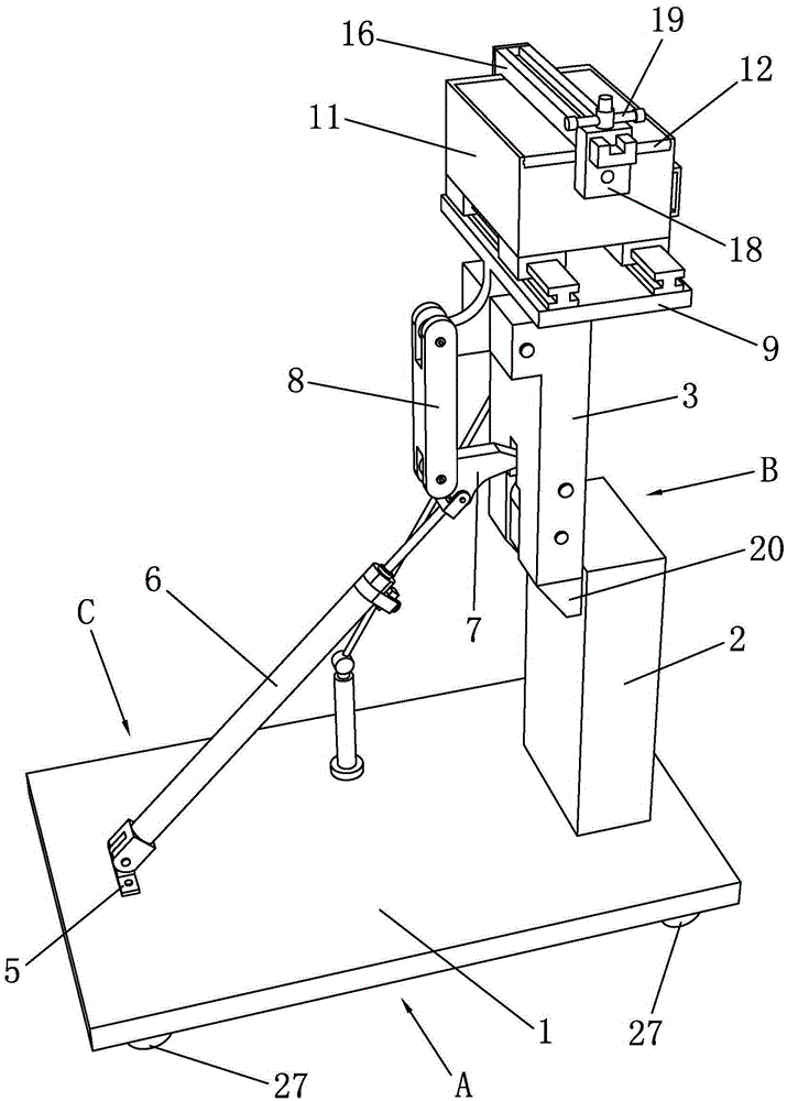
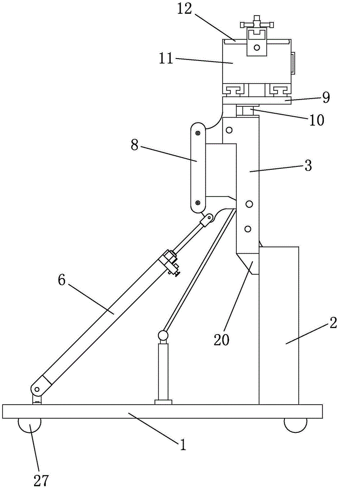
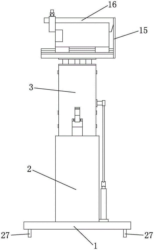
[0029] Such as Figure 1 to Figure 8 Shown is a glass conveying device of the present invention, including a base 1, the base 1 is a steel plate, and when installing components, installation holes should be reserved. The bottom of the base 1 is provided with a roller 27. The rolling of the roller 27 can adjust the distance between the glass conveying device and the truck, which is convenient for loading and unloading glass. In order to prevent the glass conveying device from rolling during conveying, a brake is generally installed on one side of the roller 27 piece.
[0030] The base 1 is provided with a supporting column 2, and the supporting column 2 is rotatably connected with a rotating arm 3. The bottom of the rotating arm 3 is provided with a contact block 20, which is in a triangular shape. When the rotating arm 3 transports glass, the rotating arm 3 3 Rotate on the supporting column 2, when the rotating arm 3 turns to the vertical state, one end of the contact stopper...
PUM
 Abstract
Description
Claims
Application Information
PatSnap Eureka turns technology decisions into work you can execute. Powered by our Innovation Knowledge Graph, it runs expert workflows across engineering, life sciences, materials and intellectual property. Get your review-ready output in minutes.


