
Segmented silicon carbide liner

A silicon carbide, segment technology, applied in the design of bonding materials and joints, in the field of silicon carbide materials, can solve problems such as material contamination

Active Publication Date: 2016-02-17
SHAANXI NON FERROUS TIAN HONG REC SILICON MATERIAL CO LTD
View PDF7 Cites 0 Cited by
  • Summary
  • Abstract
  • Description
  • Claims
  • Application Information

AI Technical Summary

Problems solved by technology

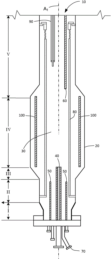
[0005] A common problem in fluidized bed reactors is that at high operating temperatures, silicon-coated particles in the fluidized bed are contaminated by materials used to construct the reactor and its components

Method used


Image

  • Segmented silicon carbide liner
  • Segmented silicon carbide liner
  • Segmented silicon carbide liner

Examples


Embodiment 1

[0122] Evaluation of Adhesive Materials

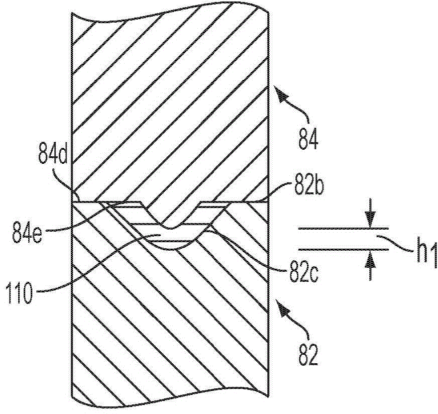
[0123] Bonding materials based on potassium and lithium silicates are commercially available, such as Ceramabond 890-K and 890-L, where K and L refer to potassium and lithium, respectively (Aremco Products, Inc., Valley Cottage, NY). Both bonding materials include fine silicon carbide particles as filler and aluminosilicate as thickener. Adhesive materials are available as pre-mixed slurries.

[0124] Mix each bonding material well before use by shaking for 5 minutes or stirring with a mechanical stirrer. Clean the surface of the silicon carbide joint with a metal brush and wipe it with a clean cloth. Use a spatula to apply the bonding material to the mating pin and box (ie tongue and groove joint). Wipe off excess adhesive material. Typically, 3 pairs of silicon carbide segments (5-8 cm long) were tested per set of conditions to ensure repeatability. Press and clamp the male and female fittings together. The clamped joints were ...


PUM


Abstract

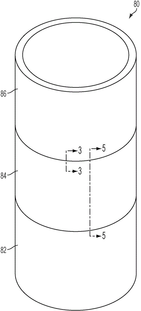
Segmented silicon carbide liners for use in a fluidized bed reactor for production of polysilicon-coated granulate material are disclosed, as well as methods of making and using the segmented silicon carbide liners. Non-contaminating bonding materials for joining silicon carbide segments also are disclosed. One or more of the silicon carbide segments may be constructed of reaction-bonded silicon carbide.

Description

technical field [0001] The present disclosure relates to silicon carbide materials, bonding materials, and joint designs for making segmented silicon carbide liners for use in fluidized bed reactors for making polysilicon-coated granular materials. Background technique [0002] Pyrolytic decomposition of silicon-containing gases in fluidized beds is an attractive method for the production of polysilicon for use in the photovoltaic and semiconductor industries due to excellent mass and heat transfer, increased deposition surface and continuous production. Compared to Siemens type reactors, fluidized bed reactors offer significantly higher production rates at a fraction of the energy expenditure. Fluidized bed reactors can be highly automated to significantly reduce labor costs. [0003] Manufacture of granular polysilicon in a fluidized bed reactor by chemical vapor deposition involving pyrolysis of silicon-containing species such as monosilane, disilane or halosilanes such ...

Claims


Application Information

Patent Timeline
Patent Type & Authority Applications(China)
IPC IPC(8): C01B33/027B01J8/24C04B35/565C04B35/63
CPCB01J8/1818B01J8/1836B01J8/1872B01J19/02B01J2208/00407B01J2208/00761B01J2208/00796B01J2219/029C01B33/027C01B33/029C01B33/03F27B15/06F27D1/0006F27D1/045B01J2208/00168B01J2219/0263C01B32/956B01J2208/00008
Inventor E·韦恩·奥斯本马修·J·米勒迈克尔·V·斯潘格勒格拉尔德·A·泽宁戈尔威廉姆·J·昂斯托特沃尔特·J·施图平
Owner SHAANXI NON FERROUS TIAN HONG REC SILICON MATERIAL CO LTD
Learn More