Strip filling method of conventional mining face goaf pumping cementing materials

A technology for strip filling and cementing materials, which is used in filling materials, mining equipment, earth-moving drilling, etc., can solve the problems of increased filling cost, poor control effect of overlying rock, and low filling body strength, and achieves safe and reliable construction process. The effect of good strip forming quality and good roadway safety

Inactive Publication Date: 2016-02-17
SHANDONG UNIV OF SCI & TECH
View PDF8 Cites 13 Cited by
  • Summary
  • Abstract
  • Description
  • Claims
  • Application Information

AI Technical Summary

Problems solved by technology

[0004] (1) The demand for gangue is large and the filling process is complicated: a large amount of gangue is required for all goaf filling. However, the underground gangue output of a mine is limited, and sometimes it cannot meet the filling demand. If the gangue from the ground gangue pile is transported to the underground for filling, It will inevitably make the downhole filling process more complicated and the filling cost will increase
[0005] (2) The cost of filling is high, which has a great impact on production: all the gobs are filled, and the filling work takes a long time, which will inevitably seriously affect the coal mining efficiency of the working face and have a great impact on production. At the same time, the filling cost will also be relatively improve
However, the main problem of this kind of filling method is that there are large gaps between the solid gangue blocks, and the early strength of the filling body is low. Only after the overlying rock layer has subsided and compacted to a certain extent can it support the roof. Therefore, it is often impossible to effectively control the subsidence of the overlying strata, and the control effect on the overlying strata is poor.

Method used


Image

  • Strip filling method of conventional mining face goaf pumping cementing materials
  • Strip filling method of conventional mining face goaf pumping cementing materials
  • Strip filling method of conventional mining face goaf pumping cementing materials

Examples


Embodiment Construction

[0037] The specific embodiments of the present invention will be further described in detail below in conjunction with examples and accompanying drawings.

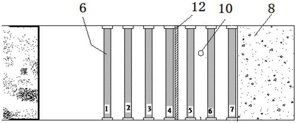
[0038] Example of embodiment: The general mining working face of a certain coal mine is 180m long, and the working face adopts a single hydraulic prop to support the roof, the prop row distance c=1.0m, and the maximum control top distance is the width of seven rows of props, which is 7m.

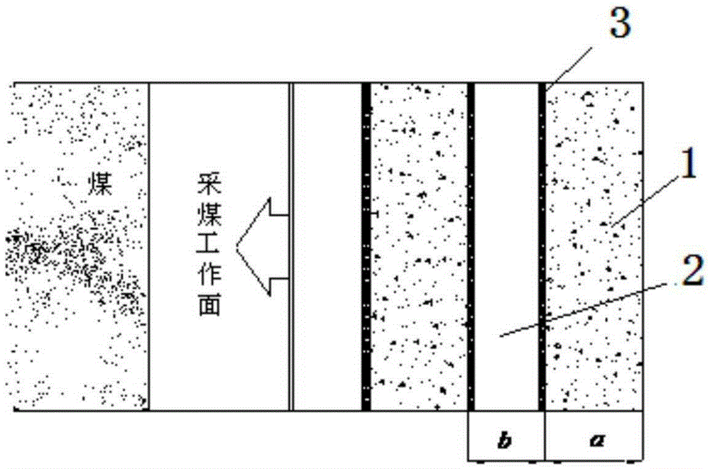
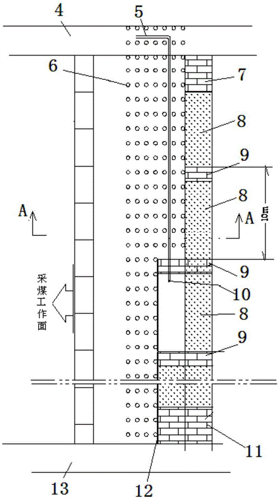
[0039] Such as figure 1 , figure 2 , image 3 As shown, a strip filling method for pumping cementing material in the goaf of a general mining face includes the following steps:

[0040] In the first step, before filling the goaf, the strip filling body 1 is designed along the advancing direction in the goaf. According to the condition of the overlying rock roof, the strip filling body 1 is determined through the theoretical calculation of mine pressure and the mechanical performance experiment of the filling body. Width a and non-filli...


PUM


Abstract

The invention discloses a strip filling method of conventional mining face goaf pumping cementing materials. The method includes: designing strip filling bodies in a goaf along an advancing direction, constructing a first small filling strip at determined strip filling body positions according to a principle that the intervals among rear four rows of support columns are filled when a conventional mining face advances to the seventh row of support columns, sequentially completing small filling sections from bottom to top along the inclination direction of the mining face in the same manner, and building an upper-end gangue wall on the lying side of an upper roadway so as to prevent gangue slurry from overflowing and form the first small filling strip; constructing a second small filling strip and the like according to the construction step of the first small filling strip until the design width of the strip filling bodies is reached. The method has the advantages that during the filling process and after the strip filling is completed, the method is good in roadway safety, good in strip forming quality, high in construction efficiency, low in filling cost, and the like.

Description

technical field [0001] The invention relates to a strip filling method, in particular to a strip filling method of cementing material strips pumped in a goaf of a general mining working face. Background technique [0002] Goaf filling mining technology is a coal mining method that processes waste gangue materials produced underground and fills them into the goaf formed after coal mining to support the overlying rock stratum and reduce rock collapse and deformation. Filling mining technology is a kind of green mining technology in mining areas. It plays a very important role in controlling the settlement of overburden rock, protecting surface land and water resources, and solving problems such as gangue environmental pollution in mining areas. [0003] Most of the current filling mining technologies use gangue materials to fill the goaf completely. However, this filling method has the following deficiencies, which limit its wide-scale application in mining enterprises, mainly...

Claims


Application Information

Patent Timeline
Patent Type & Authority Applications(China)
IPC IPC(8): E21F15/00
CPCE21F15/00
Inventor 黄万朋刘济仁李超郭忠平
Owner SHANDONG UNIV OF SCI & TECH
Why Eureka
Try Eureka