Split axial plunger pump flow distribution plate with rotatable outer sealing belt

A technology of axial plunger pump and external seal, which is applied in the direction of liquid variable capacity machinery, pumps, multi-cylinder pumps, etc., can solve the problems of cylinder overturning, unsuitable for new working conditions, and increased overturning moment, etc., to achieve Effect of avoiding leakage increase and reducing energy dissipation

Active Publication Date: 2016-02-17
ZHEJIANG UNIV
View PDF5 Cites 6 Cited by
  • Summary
  • Abstract
  • Description
  • Claims
  • Application Information

AI Technical Summary

Problems solved by technology

[0004] However, when the working conditions change in a wide range, when the swash plate inclination, speed, and pressure of the axial piston pump are adjusted in a wide range, the magnitude and direction of the overturning moment of the cylinder block also change in a wide range, especially when the pump is working at a high speed. When the displacement is large, the overturning moment caused by the centrifugal force of the plunger increases sharply (the direction of the overturning moment is different from the direction of the traditional overturning moment), and the optimal oil film design obtained at the design point is not suitable for the new working conditions, and even the cylinder Severe overturning, direct metal contact between the distribution pair, resulting in component damage

Method used


Image

  • Split axial plunger pump flow distribution plate with rotatable outer sealing belt
  • Split axial plunger pump flow distribution plate with rotatable outer sealing belt
  • Split axial plunger pump flow distribution plate with rotatable outer sealing belt

Examples


Embodiment Construction

[0023] Attached below Figure 1 to Figure 6 The present invention will be further described with specific examples.

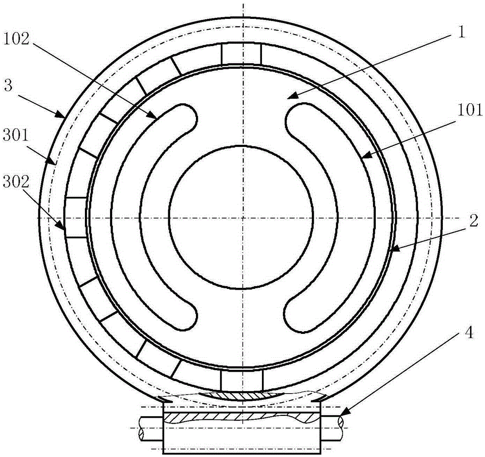
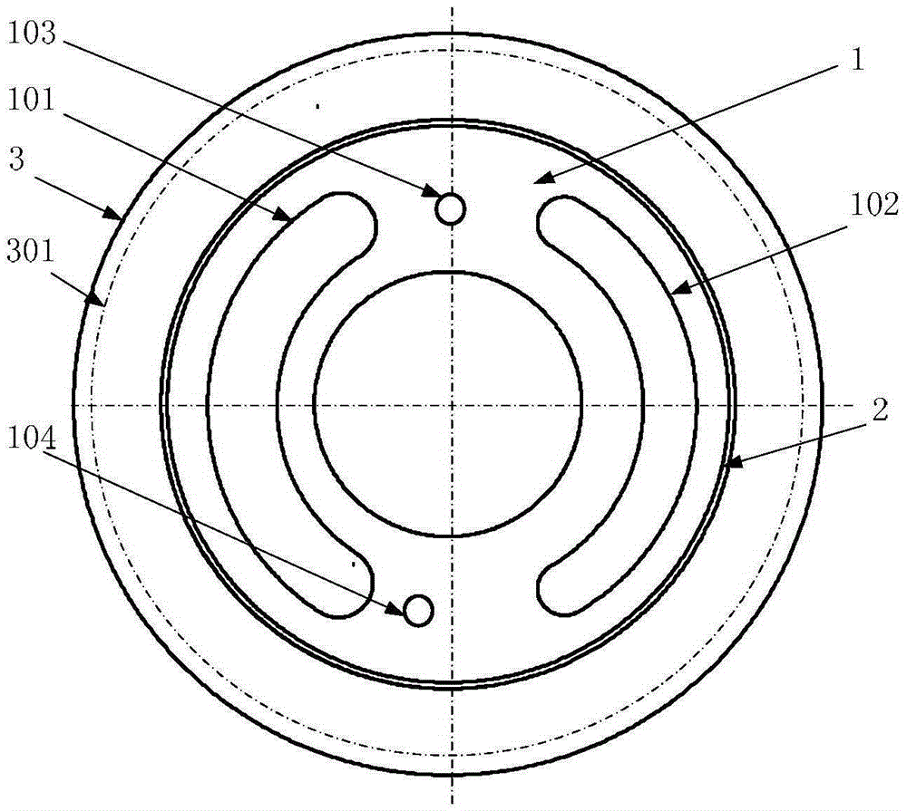
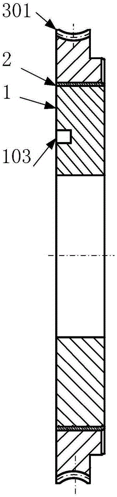
[0024] Such as figure 1 As shown, the distribution plate of the present invention is divided into an inner fixed disc 1 and a rotatable outer sealing band 3 surrounding the inner fixed disc 1 peripheral surface, and the cylindrical surface between the inner fixed disc 1 and the rotatable outer sealing band 3 passes through a sliding bearing 2 Movable connection, the two sides of the end surface of the internal fixed plate 1 are respectively provided with a low-pressure arc-shaped channel 101 connected with the pump oil suction port and a high-pressure arc-shaped channel 102 connected with the pump outlet, and the low-pressure arc-shaped channel 101 is connected with the high-pressure arc channel. The main body of the shaped through groove 102 is symmetrically located on the same annulus, such as figure 2 As shown, an upper blind hole 103 and a lower blind ho...


PUM


Abstract

The invention discloses a split axial plunger pump flow distribution plate with a rotatable outer sealing belt. The flow distribution plate is divided into an inner fixed plate and the outer rotatable sealing belt surrounding the circumferential face of the inner fixed plate, and the inner fixed plate and the outer rotatable sealing belt are connected movably through a sliding bearing. A low-pressure arc through groove and a high-pressure arc through groove are formed in the two sides of the end face of the inner fixed plate respectively, and an upper blind hole and a lower blind hole which are not symmetric are formed in the ring faces between the low-pressure arc through groove and the high-pressure arc through groove. An annular boss is arranged on the inner ring of the outer rotatable sealing belt, and a plurality of dynamic pressure supporting grooves are formed in a half of the end face of the annular boss. The peripheral face of the outer ring of the outer rotatable sealing belt is of a worm gear structure, and a worm gear is meshed with a worm outside the outer rotatable sealing belt to drive the outer rotatable sealing belt to rotate. According to the split axial plunger pump flow distribution plate, the position of the dynamic pressure sealing belt can be adjusted according to the changes of displacement, the rotating speed and the pressure of a plunger pump, so that the overturning degree of a cylinder body of the plunger pump is the minimum, direct metal contact between the cylinder body and the flow distribution plate is effectively avoided, and energy consumption at the auxiliary flow distribution position is reduced especially when the plunger pump runs in the state with the high pressure and a high rotating speed.

Description

technical field [0001] The invention relates to a flow plate of an axial plunger pump, in particular to a flow plate of an axial plunger pump with a rotatable and split outer seal. Background technique [0002] Axial piston pumps have been widely used in industries, especially aerospace and other industries, because they can realize various variable forms and can work reliably under high pressure and high speed conditions. In recent years, with the development of the hydraulic system in the direction of high power, the power density and efficiency of the hydraulic system are required to be higher and higher. It is bound to require the axial piston pump to further increase the pressure and speed, and adjust the output pressure, displacement and The speed can be matched with the load power in real time. [0003] One of the prerequisites for the axial piston pump to work reliably and efficiently under various working conditions is that each main friction pair such as plunger p...

Claims


Application Information

Patent Timeline
Patent Type & Authority Applications(China)
IPC IPC(8): F04B1/18F04B1/14
CPCF04B1/141F04B1/188
Inventor 欧阳小平李磊杨华勇
Owner ZHEJIANG UNIV
Why Eureka
Try Eureka