Hydraulic driven hydraulic test high pressure relief valve

A hydraulic test and unloading valve technology, applied in the direction of fluid pressure actuators, valve details, valve devices, etc., can solve the problems of low work efficiency, high pressure leakage of unloading valves, etc., and achieve convenient operation, strong sealing, cleverly designed effects

Active Publication Date: 2017-03-01
JIANGSU TIANYU VALVE MFG
View PDF5 Cites 0 Cited by
  • Summary
  • Abstract
  • Description
  • Claims
  • Application Information

AI Technical Summary

Problems solved by technology

At present, many downhole tool hydraulic testing devices used in oilfield production use manual unloading, which not only has low work efficiency, but also has the risk of sudden high pressure leakage when the staff operates the unloading valve.

Method used


Image

  • Hydraulic driven hydraulic test high pressure relief valve
  • Hydraulic driven hydraulic test high pressure relief valve
  • Hydraulic driven hydraulic test high pressure relief valve

Examples


Embodiment Construction

[0030] The present invention will be further described below in conjunction with accompanying drawing:

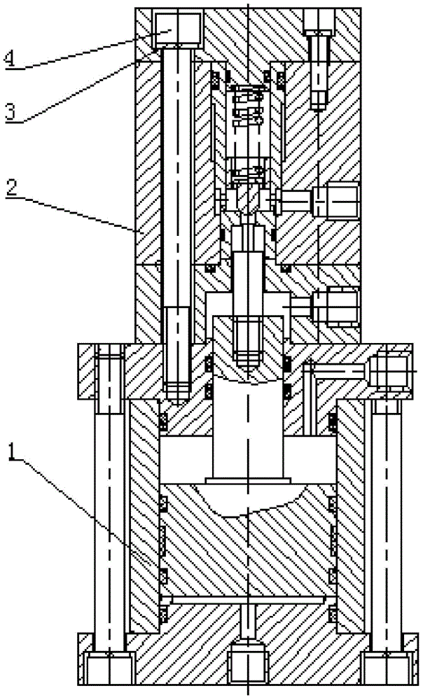
[0031] Such as figure 1 As shown, the invented hydraulically driven high-pressure unloading valve is mainly composed of hydraulic driving end 1, hydraulic end 2, first hexagon socket head screw 3 and spring washer 4, and its specific composition structure is as follows:

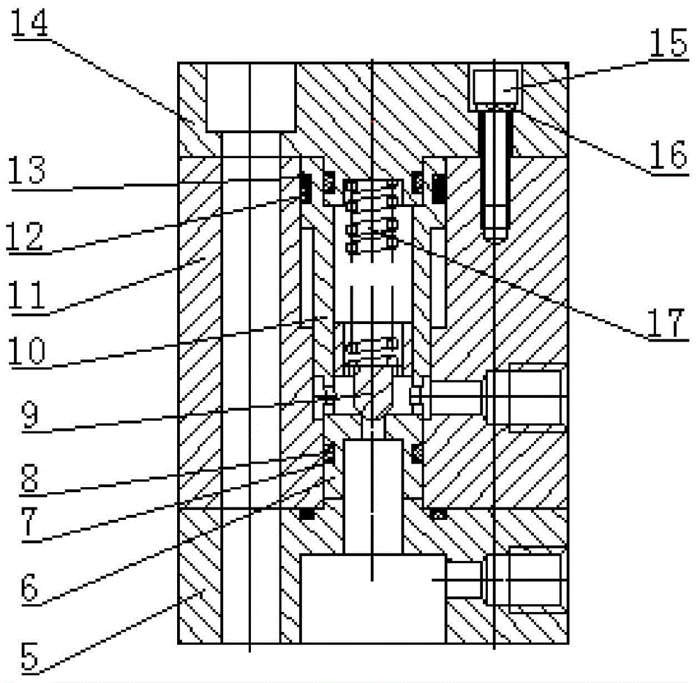
[0032] The hydraulic end consists of the hydraulic end lower cover 5, the valve seat 6, the first O-ring 7, the first retaining ring 8, the valve core 9, the guide sleeve 10, the valve sleeve 11, the second O-ring 12, and the second retaining ring 13 , Hydraulic end loam cake 14, the second hexagon socket head cap screw 15, spring washer 16, spring 17 etc. are formed.

[0033] The connection relationship of each part of the hydraulic end is: the upper cover 14 of the hydraulic end is in contact with the upper end surface 41 of the valve sleeve 11, the lower cover 5 of the hydraulic end is in contact with ...


PUM


Abstract

The invention mainly aims at providing a control device for carrying out high pressure unloading on a tested downhole tool after a pressure test is completed, and discloses a high pressure unloading valve for a hydraulic driving hydrostatic test. The high pressure unloading valve for the hydraulic driving hydrostatic test is characterized in that the high pressure unloading valve for the hydraulic driving hydrostatic test mainly comprises a hydraulic end and a hydraulic driving end; the hydraulic driving end serves as a driving component, and is mainly used to push a valve core to move during unloading, and to drive an ejection rod to drive a hydraulic sealing valve core, and an unloading channel is opened; and the hydraulic end serves as an actuating component, and is mainly used to realize the effect of self-tightening sealing on a high pressure water sealing cavity and to open a tapered-face seal under the driving of the ejection rod of the hydraulic end, thereby allowing a high pressure water flow to pass through the unloading channel. The high pressure unloading valve for the hydraulic driving hydrostatic test is ingenious in design and compact in structure; a hydraulic cylinder is controlled to drive a piston to move, the piston drives the ejection rod to drive the hydraulic sealing valve core, and the unloading channel of a high pressure tapered-face sealing pair is opened, so that the working burdens of a worker can be reduced, and the safety and reliability are improved.

Description

technical field [0001] The invention relates to a control device for high-pressure unloading after a pressure test is completed on a downhole tool to be tested, which is applied in the field of an oil field. Background technique [0002] Downhole tools are necessary supporting equipment to implement various measures for oil wells in the production process of oilfields. Their working reliability must be guaranteed. Before going into the well, they need to be tested and tested, and they can only be put into production if they fully meet the design requirements. The main function of the downhole tool hydraulic testing system is to check whether the downhole tool meets the sealing requirements in the working environment and the pressure bearing capacity in the high pressure environment. At present, many downhole tool hydraulic testing devices used in oilfield production use manual unloading, which not only has low work efficiency, but also has the danger of high pressure sudden ...

Claims


Application Information

Patent Timeline
Patent Type & Authority Patents(China)
IPC IPC(8): F15B13/02F16K31/122
CPCF15B13/02F16K31/122
Inventor 贾光政潘光绪刘旭任永良侯永强边颖聪
Owner JIANGSU TIANYU VALVE MFG
Why Eureka
Try Eureka