A system and method for automatic calibration of optical fiber gauge factor

An automatic calibration system and optical fiber strain technology, which is applied in the direction of optical devices, measuring devices, instruments, etc., can solve the problems of large error in calibration results of optical fiber strain coefficient, poor precision, cumbersome manual operation steps, etc., to improve accuracy and Effect of Gage Factor Calibration Efficiency

Active Publication Date: 2017-11-14
CHINA ELECTRONIS TECH INSTR CO LTD
View PDF5 Cites 0 Cited by
  • Summary
  • Abstract
  • Description
  • Claims
  • Application Information

AI Technical Summary

Problems solved by technology

[0003] At present, the commonly used optical fiber gauge factor calibration scheme is to use equal-intensity beam deformation to cause strain on the pasted optical fiber. According to the equal-intensity beam strain is equal to the optical fiber strain, use the pasted strain gauge to test the strain, and obtain the optical fiber gauge factor through conversion. This method Manual operation is required, the accuracy is very poor, and the way the strain gauge is pasted has a great influence on the reading of the strain data, resulting in a large error in the calibration result of the gauge coefficient, which is difficult to meet the calibration requirements; Control the displacement stage, paste the optical fiber on both sides of the displacement stage, manually move the displacement stage to stretch the optical fiber, and cause the optical fiber to strain. By measuring the moving distance of the displacement stage and the original length, the strain coefficient of the optical fiber is calculated in a physical sense. Because the original length needs to pass the length ruler test, the length error is large, and the manual operation steps are cumbersome, resulting in large errors in the calibration results of the optical fiber gauge coefficient, and the calibration efficiency is very low, which is difficult to meet the rapid calibration requirements of different optical fiber gauge coefficients in practical applications.

Method used


Image

  • A system and method for automatic calibration of optical fiber gauge factor
  • A system and method for automatic calibration of optical fiber gauge factor
  • A system and method for automatic calibration of optical fiber gauge factor

Examples


Embodiment Construction

[0047] The present invention will be further described below in conjunction with the accompanying drawings and embodiments.

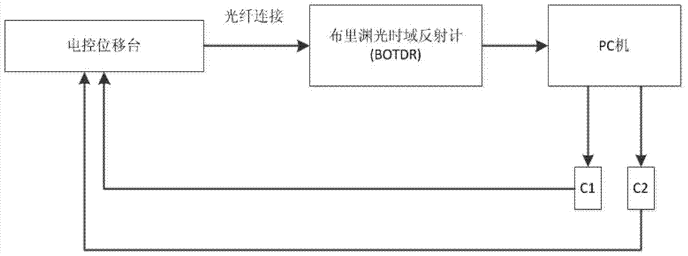
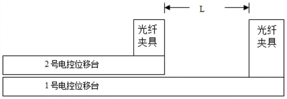
[0048] In the automatic calibration method of optical fiber strain coefficient proposed by the present invention, devices such as computer-controlled electronically controlled displacement stage, dual-frequency laser interference device, Brillouin optical time domain reflectometer and the like are used to complete the automatic calibration of optical fiber strain coefficient. The device is connected as figure 1 shown. The movement of the electronically controlled displacement stage is used to generate strain on the optical fiber, and the original length and displacement length of the optical fiber are measured by a dual-frequency laser interferometry device, and the displacement length of the displacement stage is corrected twice in combination with the grating ruler.

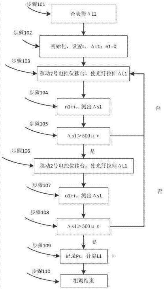
[0049] This method will automatically read the central frequency shift distributio...


PUM


Abstract

The invention discloses a system and method for automatic calibration of an optical fiber strain coefficient. By reading a center frequency shift distribution curve tested by a Brillouin light time domain reflectometer, according to an estimated value of the original length of an optical fiber, the automatic identification of a strain area is finished by changing displacement lengths at large intervals by means of a strain area recognition algorithm; after the strain area is recognized, the displacement lengths are changed sequentially from large to small, so that the optical fiber sequentially generates strain from large to small, a theoretical strain value of the optical fiber and an actual Brillouin spectrum frequent shift value are calculated by utilizing an optical fiber strain coefficient analytical algorithm, and all-automatic calibration of the optical fiber strain coefficient is achieved. According to the system and method for automatic calibration of the optical fiber strain coefficient, the all-automatic calibration of the optical fiber strain coefficient can be achieved, and the strain coefficient calibration accuracy and strain coefficient calibration efficiency are improved effectively.

Description

technical field [0001] The invention relates to an automatic calibration system and method for optical fiber strain coefficient. Background technique [0002] In the optical fiber sensing system, the Brillouin optical time domain reflectometer (abbreviated as BOTDR) is an indispensable testing instrument. In the process of using it, the gauge coefficient of the optical fiber under test must be determined before the optical fiber can be accurately calculated. Strain distribution, and this coefficient is related to the material of the optical fiber. It is a physical parameter of the optical fiber itself, which cannot be directly tested, but can only be obtained through indirect testing and calibration. [0003] At present, the commonly used optical fiber gauge factor calibration scheme is to use equal-intensity beam deformation to cause strain on the pasted optical fiber. According to the equal-intensity beam strain is equal to the optical fiber strain, use the pasted strain g...

Claims


Application Information

Patent Timeline
Patent Type & Authority Patents(China)
IPC IPC(8): G01B11/16
CPCG01B11/161
Inventor 袁明吴寅初闫继送代彬张平
Owner CHINA ELECTRONIS TECH INSTR CO LTD
Why Eureka
Try Eureka