
Automatic shielding test device and test flow line thereof

A technology of testing devices and shielding boxes, which is applied in the direction of shielding devices, measuring device shells, electromagnetic field characteristics, etc., can solve the problems of low equipment utilization, low testing efficiency, and high equipment costs, and achieve high testing efficiency, fast action, and control simple effect

Active Publication Date: 2016-02-17
SHENZHEN JIACHEN TECH
View PDF7 Cites 5 Cited by
  • Summary
  • Abstract
  • Description
  • Claims
  • Application Information

AI Technical Summary

Problems solved by technology

[0006] The purpose of the present invention is to propose a shielding box that can realize the shielding box in order to solve the problems of low test efficiency, low equipment utilization rate and high manpower and equipment cost caused by the discontinuous test process in the existing manual shielding test process of electronic communication products. The flow-in and out-feeding system connects each test process through a conveyor belt to form a continuous assembly line test form, which effectively improves the test efficiency and equipment utilization. The online automatic shielding test device and the test assembly line composed of the online automatic shielding test device as the core , through the application of the online automated shielding test device and the test assembly line composed of the online automated shielding test device as the core, it can reduce labor and equipment costs, improve equipment utilization and production efficiency, and ensure the safety of the product during the test process. Purpose of test process automation

Method used


Image

  • Automatic shielding test device and test flow line thereof
  • Automatic shielding test device and test flow line thereof
  • Automatic shielding test device and test flow line thereof

Examples


Embodiment Construction

[0047] In order to illustrate the technical solution of the present invention more clearly, the technical solution of the present invention will be further described in detail below in conjunction with the accompanying drawings and embodiments. Obviously, the following descriptions are only some embodiments of the present invention. In other words, other embodiments can also be obtained according to these embodiments without paying creative efforts.

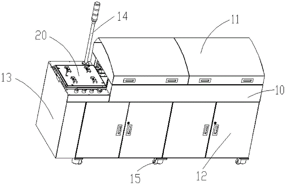
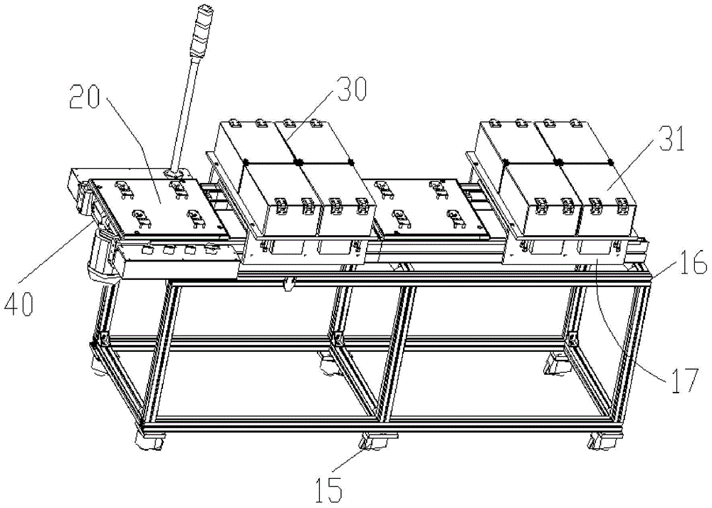
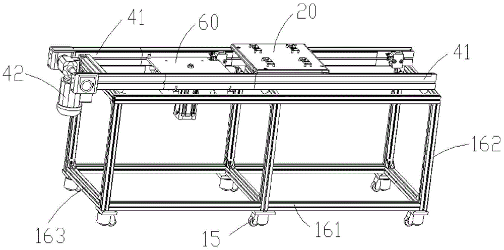
[0048] refer to figure 1 , figure 2 , an on-line automatic shielding test device, including a cabinet 10, and at least one shielding test unit 30 installed in the cabinet 10, a first rail conveyor belt 40, a tray 20, a jacking mechanism 60 and a test control mechanism, the shielding test unit 30. The first track-type conveyor belt 40 and the jacking mechanism 60 are respectively electrically connected to the test control mechanism and coordinate operations under the control of the test control mechanism;

[0049] The shielding...


PUM


Abstract

The invention discloses an online automatic shielding test device and a test flow line thereof. The device comprises a cabinet, at least one shielding test unit, a first track type conveying belt, a tray, a lifting-up mechanism and a test control mechanism, wherein the at least one shielding test unit, the first track type conveying belt, the tray, the lifting-up mechanism and the test control mechanism are mounted in the cabinet, the at least one shielding test unit, the first track type conveying belt and the lifting-up mechanism are respectively electrically connected with the test control mechanism, and coordination work under control of the test control mechanism is realized. According to the device, the structure of a shielding casing is designed in a brand new mode, a bottom portion feeding structure mode is employed to ingeniously solve a problem that material feeding and discharging of the shielding casing cannot be realized by utilizing the conveying belt, each test element for shielding tests on electronic communication products is integrated through the track type conveying belt onto a flow line by taking the tray as a medium, control is simple, motion is rapid, and the stroke position is precise.

Description

technical field [0001] The invention relates to electronic communication product testing equipment, in particular to an electronic communication product online automatic shielding testing equipment and a testing assembly line. Background technique [0002] Electromagnetic Interference (EMI) appears along with the development of electronics and electrical technology, and there will be electromagnetic interference in all electronic and electrical technology fields. Electromagnetic interference generated by electronic and electrical systems or equipment in extensive use will affect human health, and will also affect and harm the safety and reliability of electronic and electrical systems or equipment. The harsh electromagnetic environment often makes electronic and electrical systems or equipment unable to work normally, and even causes failures and accidents, or affects the data of electronic product testing. [0003] However, with the improvement of the accuracy requirements...

Claims


Application Information

Patent Timeline
IPC IPC(8): G01R1/18G01R1/04G01R29/08
Inventor 伍连保夏禺陈天辉
Owner SHENZHEN JIACHEN TECH
Features
  • Generate Ideas
  • Intellectual Property
  • Life Sciences
  • Materials
  • Tech Scout
  • Unparalleled Data Quality
  • Higher Quality Content
  • 60% Fewer Hallucinations
Learn More