
Optical lens

An optical lens and lens technology, applied in the field of optical lens, can solve the problems of high optical performance, poor image clarity, poor imaging condition matching, etc., and achieve the effect of high optical performance

Active Publication Date: 2016-02-17
ZHEJIANG DAHUA TECH
View PDF5 Cites 8 Cited by
  • Summary
  • Abstract
  • Description
  • Claims
  • Application Information

AI Technical Summary

Problems solved by technology

[0004] At present, the resolution level of existing zoom optical lenses in visible light mode can only meet the requirements of cameras with less than 5 million pixels; and when switching to infrared mode for image acquisition at night, the confocal performance is very poor, resulting in optical lens acquisition at night The sharpness of the image is worse than the sharpness of the image acquired under visible light conditions
The main reasons for this phenomenon are: the structure of the existing zoom optical lens, focal power distribution, optical glass refractive index and dispersion coefficient and other parameters do not match well with the imaging conditions, making the optical lens spherical aberration, coma aberration , astigmatism, field curvature, chromatic aberration of magnification, and positional chromatic aberration have not been well corrected, so that higher optical performance cannot be achieved
[0005] Therefore, the zoom optical lens in the prior art cannot meet the development needs of current and future ultra-high-definition security video surveillance systems

Method used


Image

  • Optical lens
  • Optical lens
  • Optical lens

Examples


Embodiment Construction

[0055]The following will clearly and completely describe the technical solutions in the embodiments of the present invention with reference to the accompanying drawings in the embodiments of the present invention; obviously, the described embodiments are only some of the embodiments of the present invention, not all of them. Based on the embodiments of the present invention, all other embodiments obtained by persons of ordinary skill in the art without making creative efforts belong to the protection scope of the present invention.

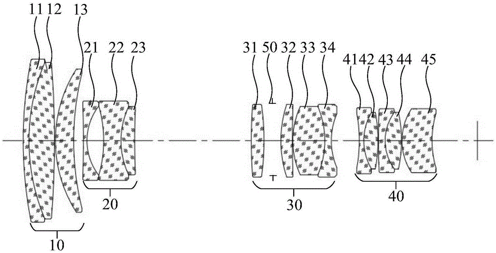
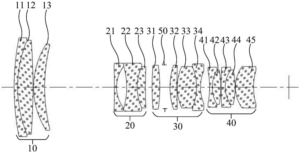
[0056] Such as Figure 1a and Figure 1b As shown, the specific embodiment of the present invention provides an optical lens, which includes in sequence from the object side to the image side along the optical axis: a first lens group 10 with a positive refractive power, and a second lens group with a negative refractive power 20. The third lens group 30 with positive refractive power, and the fourth lens group 40 with positive refractive power, w...


PUM


Abstract

The invention relates to the technical field of optical imaging, and discloses an optical lens. The optical lens successively comprises a first lens group with positive focal power, a second lens group with negative focal power, a third lens group with positive focal power and a fourth lens group with positive focal power from an object side to an image side along the direction of an optical axis. Through designing the successive arrangement sequence of each optical lens from the object side to the image side, focal power distribution of each optical lens and the like, such parameters as the structural form of a zooming optical lens, focal power distribution, a refractive index of optical glass, a dispersion coefficient and the like are enabled to match imaging conditions well, spherical aberration, coma, astigmatism, field curvature, chromatic difference of magnification and position aberration of the optical lens are well corrected, the optical lens can meet a higher resolution demand and achieve a better infrared night vision effect, all-weather ultrahigh-resolution video monitoring is realized, and the development demand of an ultrahigh-resolution safety protection monitoring system at present and in the future can be satisfied.

Description

technical field [0001] The invention relates to the technical field of optical imaging, in particular to an optical lens. Background technique [0002] With the development of the security monitoring industry, people have higher and higher requirements for the quality of monitoring information, especially for the clarity of monitoring images. [0003] In recent years, with the technological innovations and breakthroughs in data transmission technology, data storage technology, image processing technology and high-definition television display technology, it has become possible to realize ultra-high-definition video surveillance with 4K resolution, and it will become a future development trend; This requires the lens (optical lens) to have a higher resolution to meet the imaging requirements of the 4K camera. [0004] At present, the resolution level of existing zoom optical lenses in visible light mode can only meet the requirements of cameras with less than 5 million pixel...

Claims


Application Information

Patent Timeline
IPC IPC(8): G02B13/00G02B13/14G02B15/15
CPCG02B13/00G02B13/14G02B15/15
Inventor 刘凯丁洪兴
Owner ZHEJIANG DAHUA TECH
Learn More