Electrode tab clamping device for battery formation
A clamping device and battery formation technology, which is applied in the manufacture of battery pack components, non-aqueous electrolyte batteries, and electrolyte batteries, etc., can solve the problems of inconvenient contact, difficult guarantee, short circuit, etc. well-structured effect
- Summary
- Abstract
- Description
- Claims
- Application Information
AI Technical Summary
Problems solved by technology
Method used
Image

Examples
Embodiment 1
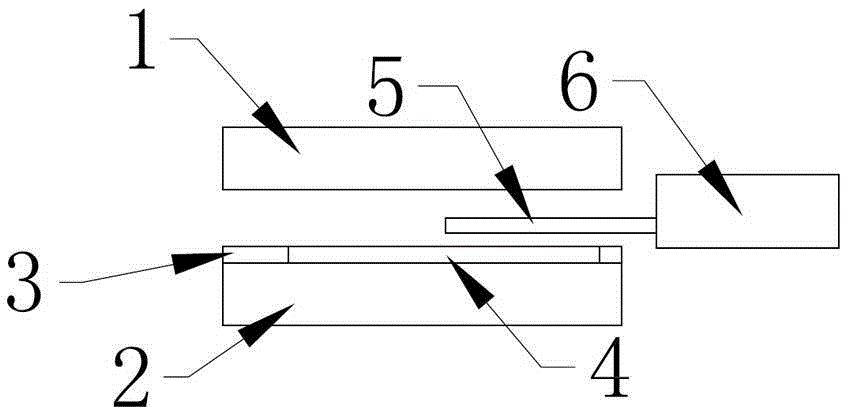
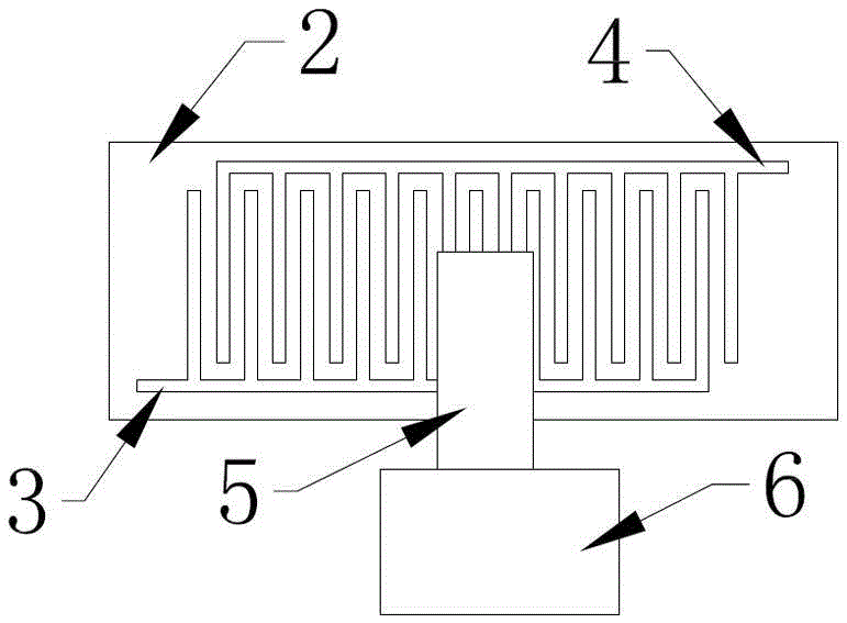
[0013] according to figure 1 , figure 2 , image 3 , Figure 4 As shown, the present invention is based on upper pressing plate 1, lower pressing plate 2, voltage conducting layer 3, and current conducting layer 4. It is characterized in that said voltage conducting layer 3 and current conducting layer 4 are respectively divided into ten conductive strips. , and are evenly spaced to form conductive regions, and then connected to the formed conductive layers through respective conductive buses; the conductive regions of the voltage conductive layer 3 and the conductive regions of the current conductive layer 4 leave gaps through their respective conductive strips to alternately correspond Engage to form the tab clamping area, so that the lithium battery 6 can be in contact with the voltage conducting layer 3 and the current conducting layer 4 at the same time when the tab 5 is partially contacted in the tab clamping area. The conductive strips of the voltage conductive laye...
Embodiment 2
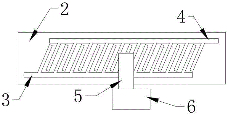
[0015] Basically the same as embodiment 1, the difference is: the conductive strips of the voltage conducting layer 3 and the current conducting layer 4 are arranged horizontally, and the conducting strips are connected to the conductive bus obliquely.
[0016] The technical solution of the present invention records that the conductive surface of the tab clamping device is divided into two groups, one group of current lines and one group of voltage lines, and then the two groups of lines are divided and thinned into one by one conductive lines, and then vertically vertical, vertically inclined, The horizontal vertical and horizontal inclined four ways are alternately arranged to form clamping conductive areas. Through this design, it is ensured that when the upper and lower pressure plates of the tab clamping device are closed, only one tab of the battery is required to be generated in the clamping area. At the same time, the area of this local contact area is larger than the...
PUM
 Abstract
Description
Claims
Application Information
 - R&D
- Intellectual Property
- Life Sciences
- Materials
- Tech Scout
- Unparalleled Data Quality
- Higher Quality Content
- 60% Fewer Hallucinations
Browse by: Latest US Patents, China's latest patents, Technical Efficacy Thesaurus, Application Domain, Technology Topic, Popular Technical Reports.
© 2025 PatSnap. All rights reserved.Legal|Privacy policy|Modern Slavery Act Transparency Statement|Sitemap|About US| Contact US: help@patsnap.com