
Semiconductor scintillation detector

一种光探测器、导体的技术,应用在仪器、测量装置、科学仪器等方向,能够解决实践性复杂化等问题

Active Publication Date: 2016-02-17
KONINKLJIJKE PHILIPS NV
View PDF7 Cites 22 Cited by
  • Summary
  • Abstract
  • Description
  • Claims
  • Application Information

AI Technical Summary

Problems solved by technology

Safety issues associated with the use of large volumes of cooled or pressurized liquid xenon further complicate its practical use in, for example, PET imaging systems

Method used


Image

  • Semiconductor scintillation detector
  • Semiconductor scintillation detector
  • Semiconductor scintillation detector

Examples


Embodiment Construction

[0042] The invention comprising a semiconductor scintillator element and a photodetector is described in relation to a PET imaging system in order to provide a radiation detection device for detecting gamma-ray radiation quanta or X-ray radiation quanta with good timing accuracy and good energy resolution. However, it should also be realized that the invention also applies to X-ray imaging systems, in particular spectral CT imaging systems.

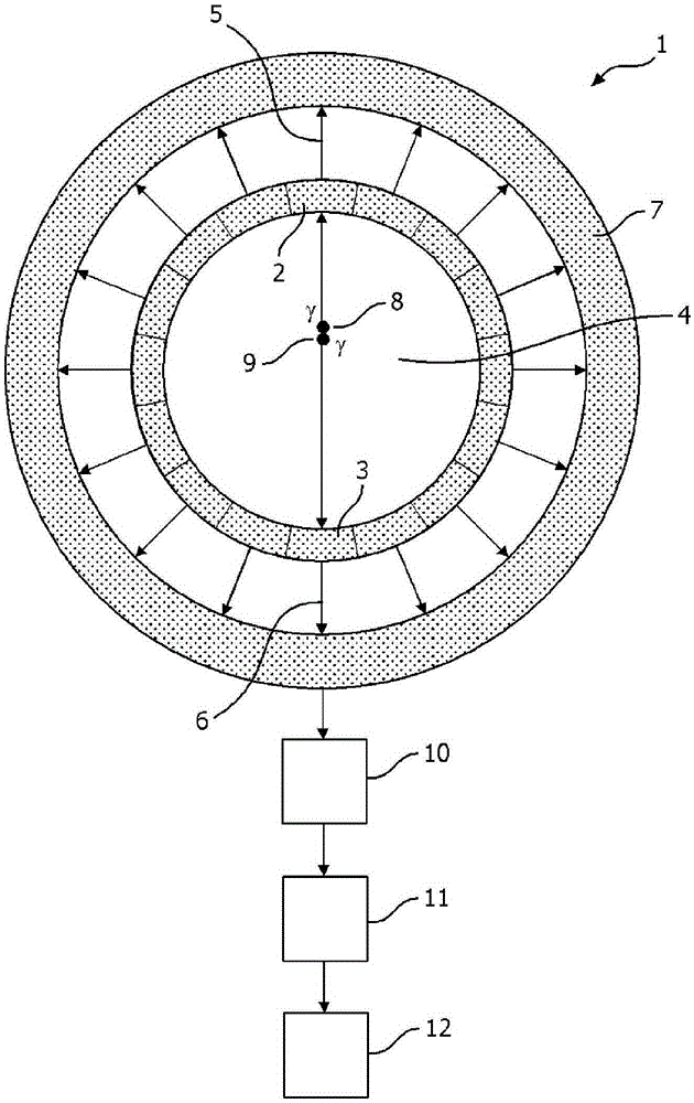
[0043] figure 1 An exemplary PET imaging system according to certain aspects of the invention is illustrated. The radiation detection device of the present invention can be used, for example, in figure 1 in the system shown in the figure. exist figure 1 1 , a PET imaging system 1 comprises a plurality of gamma radiation detection devices 2 , 3 arranged radially with respect to an imaging region 4 to receive gamma radiation (also called gamma photons) from the imaging region 4 . The plurality of gamma radiation detection devices each g...


PUM


Abstract

The present invention relates to a radiation detection device for detecting gamma or x-ray radiation quanta with improved timing accuracy and improved energy resolution. The radiation detection device finds application in the detection of gamma and x-ray radiation and may be used in the field of PET imaging, and in spectral CT. The radiation detection device includes a semiconductor scintillator element and a photodetector. The photodetector is in optical communication with the scintillator element. The scintillator element has two mutually opposing faces; a cathode is in electrical communication with one of the two faces and an anode is in electrical communication with the other of the two faces.

Description

technical field [0001] The invention relates to a device for the detection of gamma-ray or X-ray radiation quanta. A system and computer readable medium for use in accordance with the device are also disclosed. The invention finds particular application in the detection of radiation quanta in the field of nuclear imaging and X-ray imaging. More specifically, the invention applies to PET imaging systems and spectral CT imaging systems. Background technique [0002] Conventionally, detectors for ionizing radiation such as gamma-ray radiation quanta and X-ray radiation quanta used in eg PET imaging systems or X-ray imaging systems include scintillator elements and photodetectors. The scintillator element receives radiation quanta and converts each radiation quanta into a pulse of infrared, visible or ultraviolet light that is detected by a photodetector. The electrical pulses obtained from the photodetector are then analyzed to determine the properties of the radiation quant...

Claims


Application Information

Patent Timeline
Patent Type & Authority Applications(China)
IPC IPC(8): G01T1/24G01T1/20G01T1/29
CPCG01T1/24G01T1/241G01T1/249G01T1/2985G01T1/20183G01T1/20185
Inventor H·K·维乔雷克C·R·龙达L·R·瓦伦贝格M·E·梅辛S·汉森B·J·A·厄赫斯特兰德A·H·C·林德贝格N·G·艾琳R·T·哈尔贝格
Owner KONINKLJIJKE PHILIPS NV
Learn More