Supercharge Your Innovation With Domain-Expert AI Agents!

Scrap collecting workbench with discharging holes

A blanking hole and worktable technology, applied in the field of parts processing, can solve the problems of waste accumulation and easy accumulation of waste, and achieve the effect of avoiding accumulation.

Inactive Publication Date: 2016-02-24
LUZHOU YUANCHENG ENG MACHINERY CO LTD
View PDF8 Cites 8 Cited by
  • Summary
  • Abstract
  • Description
  • Claims
  • Application Information

AI Technical Summary

Problems solved by technology

[0004] The purpose of the present invention is to provide a waste collection workbench with a drop hole, which solves the problem of waste piled up during the processing of mechanical parts in the prior art, and realizes convenient and fast cleaning and recycling of the workbench The purpose of the waste on
Aiming at the problem that waste chips are easy to accumulate around in the existing mechanical parts processing workbench, the present invention provides a waste collection workbench with a drop hole, through which the waste chips are dropped to In the drawer, realize the purpose of quick cleaning and recycling waste

Method used


Image

  • Scrap collecting workbench with discharging holes
  • Scrap collecting workbench with discharging holes
  • Scrap collecting workbench with discharging holes

Examples


Embodiment 1

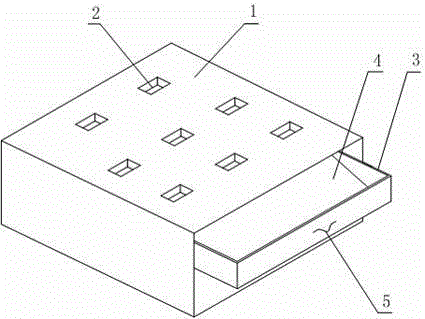
[0018] Such as figure 1 Shown is a waste collection workbench with a drop hole, a waste collection workbench with a drop hole, including a table body 1 for installing a fixture and a power head, and the table body 1 is internally provided with The drawer 3 pulled away from the side of the table body 1, the bottom surface of the drawer 3 is provided with a guide plate 4 inclined downward from the inside to the outside, and the upper surface of the table body 1 is provided with a number of blanking holes 2, the blanking holes 2 communicates with the inside of the drawer 3, and the drawer 3 is provided with a handle 5. In the use of this embodiment, the drawer 3 is pushed to the inside of the table body 1, and the normal processing work is carried out after placing the fixture and the power head on the table body 1, and the waste chips generated in the process are removed. Fall onto the table body 1, and fall into the drawer 3 inside the table body 1 through the blanking hole 2....

Embodiment 2

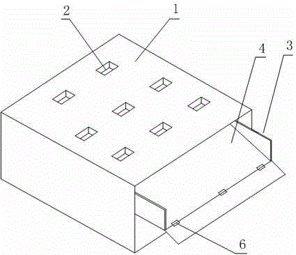
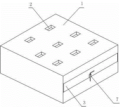
[0020] Such as figure 2 and image 3 Shown is a waste collection workbench with a drop hole, on the basis of Embodiment 1, the outward side of the drawer 3 is connected to its bottom surface through a hinge 6; the outward side of the drawer 3 is connected through a latch 7 is connected with the side of table body 1. Conventionally, the waste chips collected in the drawer 3 can only be dumped after the drawer 3 is taken out after the processing is completed or the work is stopped. However, in this embodiment, the user can artificially release the fixation of the latch 7, and through the hinge 6, the outer surface of the drawer 3 becomes an opening, so that waste can be directly discharged, and during the processing It is also possible to discharge waste at the same time, which is convenient for use; when it is not necessary to discharge waste in time, this embodiment can also ensure the integrity of the four sides of the drawer through the latch 7 to ensure its storage capac...


PUM


Abstract

The invention discloses a scrap collecting workbench with discharging holes. The scrap collecting workbench comprises a workbench body used for mounting a clamp and a power head. A drawer which is pulled open from the side face of the workbench body is arranged in the workbench body, a guiding plate which inclines downwards from inside to outside is arranged on the bottom face of the drawer, and a plurality of discharging holes are formed in the upper surface of the workbench body and communicated with the inside of the drawer. By means of the scrap collecting workbench with the discharging holes, the problem that scraps generated in the machine part machining process in the prior art are stacked everywhere is solved, and the purpose of sweeping and recovering scraps on a machining workbench conveniently and quickly is achieved.

Description

technical field [0001] The invention relates to the field of component processing, in particular to a waste collection workbench with a blanking hole. Background technique [0002] Mechanical components, also known as mechanical components, are inseparable individual parts that make up machinery and machines. It is the basic unit of machinery, such as various bearings, valves, linkages, transmissions, and meshing devices. Long before the appearance of modern machinery, there were already many prototypes of mechanical parts, but as a subject, mechanical parts were separated from mechanical construction and mechanics. With the development of the machinery industry, the emergence of new design theories and methods, new materials, and new processes, mechanical parts have entered a new stage of development, and are now inseparable from people's daily lives. However, for mechanical parts, it must be processed on a machine tool or workbench with a certain processing capacity, and ...

Claims


Application Information

Patent Timeline
IPC IPC(8): B25H1/02
CPCB25H1/02
Inventor 马赟
Owner LUZHOU YUANCHENG ENG MACHINERY CO LTD
Features
  • R&D
  • Intellectual Property
  • Life Sciences
  • Materials
  • Tech Scout
  • Unparalleled Data Quality
  • Higher Quality Content
  • 60% Fewer Hallucinations
Learn More