Push rod type indicating device and rubber plug falling indication cementing head

An indicating device and push rod technology, which is used in wellbore/well components, earthwork drilling, sealing/packing, etc., can solve the problem that the rubber plug cannot leave the cement head normally, cannot touch the bottom of the well, and leave a lot of ash. It can reduce the cost of cementing and workover, improve the quality of cementing, and improve the success rate.

Active Publication Date: 2016-02-24
BC P INC CHINA NAT PETROLEUM CORP +1
View PDF8 Cites 3 Cited by
  • Summary
  • Abstract
  • Description
  • Claims
  • Application Information

AI Technical Summary

Problems solved by technology

[0004] The present invention provides a push rod type indicator device and a rubber plug to indicate the cement head downward, which overcomes the above-mentioned deficiencies in the prior art, and can effectively solve the problem of existing cement The head is easy to cause the rubber plug to not leave the cement head normally, resulting in serious accidents such as failure to bump pressure and a large amount of ash plug left at the bottom of the well; the problem of complex structure and high cost

Method used


Image

  • Push rod type indicating device and rubber plug falling indication cementing head
  • Push rod type indicating device and rubber plug falling indication cementing head
  • Push rod type indicating device and rubber plug falling indication cementing head

Examples


Embodiment 1

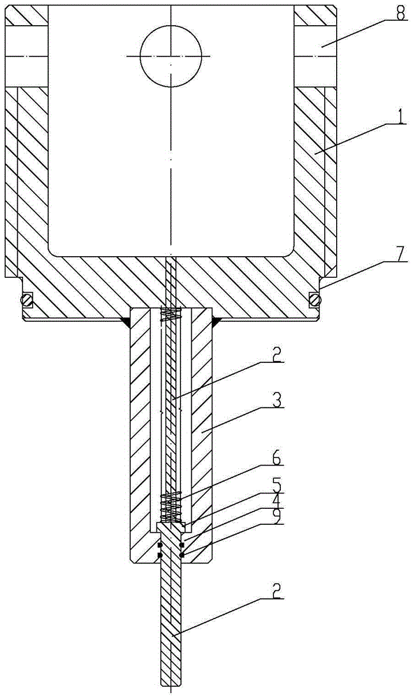
[0023] Example 1, as attached figure 1 , 2 3, the push rod type indicating device includes a gland 1, a push rod 2 and a sleeve body 3 with an opening facing upward; a sleeve body 3 is fixedly connected to the lower end of the gland 1, and the bottom of the gland 1 is provided with The connecting hole of the sleeve body 3 is integrally fixed with a retaining ring 4 on the inner side of the lower end of the sleeve body 3, and a ring block 5 is integrally fixed on the lower outer side of the push rod 2, and the ring block 5 of the push rod 2 is seated on the sleeve body On the retaining ring 4 of 3, the lower part of the push rod 2 is located outside the sleeve body 3, the upper end of the push rod 2 is located in the mounting hole of the gland 1, and the push rod 2 above the ring block 5 in the sleeve body 3 is installed with Compression spring 6. In this way, under normal circumstances, the compression spring 6 is in a natural state, the lower end of the compression spring 6 c...

Embodiment 2

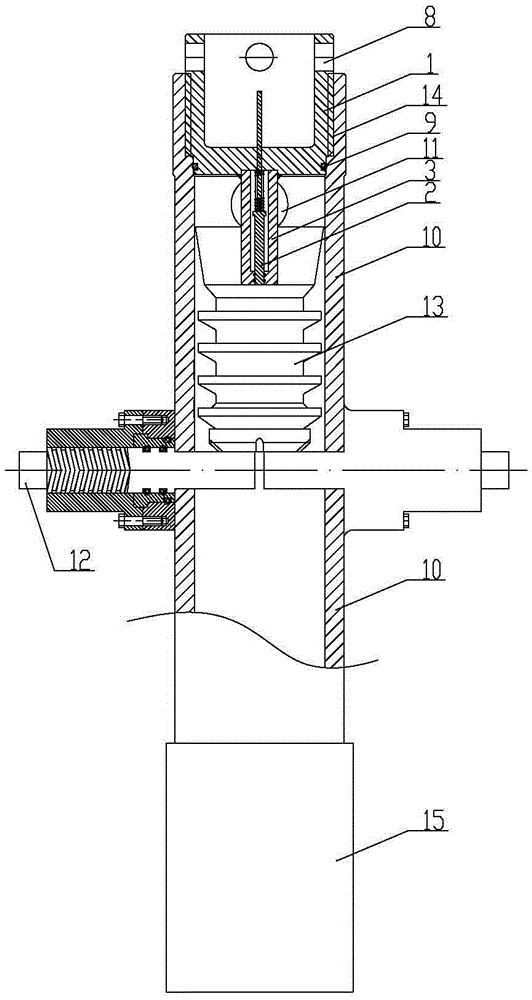
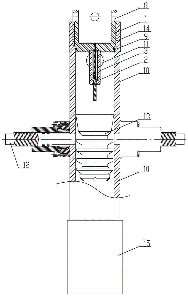
[0029] Example 2, as attached figure 2 As shown, the rubber plug using a push rod type indicating device to downwardly indicate the cement head includes a push rod type indicating device and a cement head body 10; the lower outer side of the gland 1 and the upper end inner side of the cement head body 10 are fixedly installed together. The upper part of the cement head body 10 is provided with a slurry replacement hole 11 communicating with the cavity of the cement head body 10, a stop pin 12 is fixedly installed in the middle of the cement head body 10, and a rubber plug 13 is arranged in the cavity of the cement head body 10 , The rubber plug 13 is seated on the stop pin 12 and is located between the mixing hole 11 and the stop pin 12, and the lower end of the push rod 2 is pressed against the rubber plug 13. The cement head body 10, the stop pin 12 and the rubber plug 13 are all the prior art; through the push rod type indicating device, the cement head body 10, the stop pin...


PUM


Abstract

The invention relates to the technical field of cementing tools, and provides a push rod type indicating device and a rubber plug falling indication cementing head. The push rod type indicating device comprises a gland with an upward opening, a push rod and a sleeve; the lower end of the gland is fixedly connected with the sleeve, the bottom of the gland is provided with an installation hole communicated with a cavity of the sleeve, the inner side of the lower end of the sleeve is integrally fixed with a baffle ring, and the outer side of the lower portion of the push rod is integrally fixed with an annular clamping block. According to the push rod type indicating device and the rubber plug downward indication cementing head, the structure is reasonable and compact, through matched usage of the push rod type indicating device, a cementing head body, a stop pin and a rubber plug, the purpose of judging whether the rubber plug falls or not by observing stretching out and retracting of the push rod when rubber plug pressing is performed in well cementing operation is achieved, and the serious problems that pressure bumping cannot be performed and a large number of cement plugs are reserved in the downhole due to the fact that the rubber pug cannot fall are prevented from occurring; the advantages of being safe and reliable is achieved, operation is facilitated, the well cementing construction success rate is increased, the well cementing quality is improved, and meanwhile the well cementing and repairing cost is greatly reduced.

Description

technical field [0001] The invention relates to the technical field of cementing tools, and relates to a push rod-type indicating device and a rubber plug to indicate the cement head downward. Background technique [0002] Cement head is a wellhead tool commonly used in cementing construction, and plays a very important role in the cementing process. In the process of cementing the rubber plug in the existing conventional cement head, it is usually impossible to judge whether the rubber plug has fallen correctly. It often happens that the rubber plug fails to leave the cement head normally because the stopper pin is not opened in place or other reasons, resulting in Serious accidents such as inability to bump and leave a large amount of ash plugs at the bottom of the well. [0003] At present, there are also cement heads at home and abroad that can indicate the downward direction of the rubber plug. During the working process, the cement slurry easily enters the cavity of t...

Claims


Application Information

Patent Timeline
Patent Type & Authority Applications(China)
IPC IPC(8): E21B33/13
CPCE21B33/13
Inventor 林建增苏洪生郑永生彭为刘正勇符晓东傅特于有玉
Owner BC P INC CHINA NAT PETROLEUM CORP
Why Eureka
Try Eureka