Engine exhaust brake system

An exhaust brake and engine technology, applied in the direction of engine components, machines/engines, mechanical equipment, etc., can solve the problems of difficult space layout and increased weight, and achieve integrated design, reduce weight, and maximize functions. Effect

Active Publication Date: 2016-02-24
WEICHAI POWER CO LTD
View PDF5 Cites 23 Cited by
  • Summary
  • Abstract
  • Description
  • Claims
  • Application Information

AI Technical Summary

Problems solved by technology

[0005] The technical problem to be solved by the present invention is that the exhaust cam and the brake cam are sep

Method used


Image

  • Engine exhaust brake system
  • Engine exhaust brake system
  • Engine exhaust brake system

Examples


Embodiment Construction

[0028] In order to make the purpose, technical solutions and advantages of the embodiments of the present invention clearer, the technical solutions in the embodiments of the present invention will be clearly and completely described below in conjunction with the drawings in the embodiments of the present invention. Obviously, the described embodiments It is a part of embodiments of the present invention, but not all embodiments. Based on the embodiments of the present invention, all other embodiments obtained by persons of ordinary skill in the art without making creative efforts belong to the protection scope of the present invention.

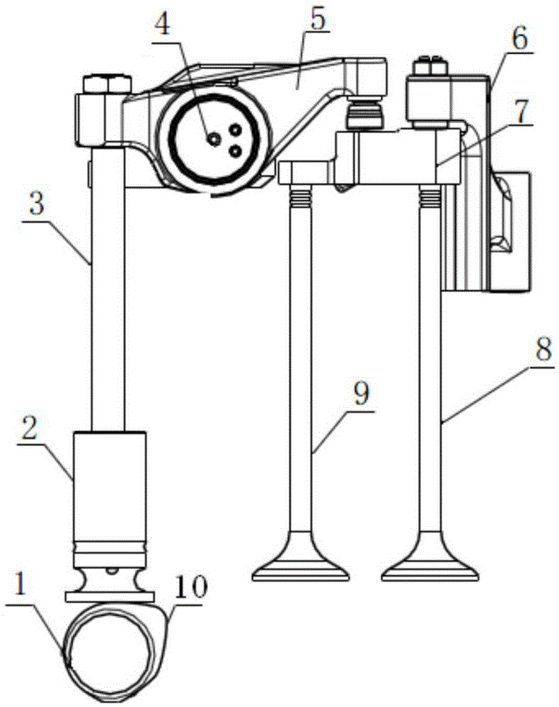
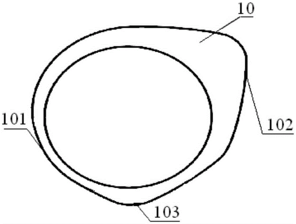
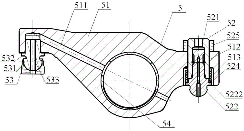
[0029] Such as Figure 1 to Figure 7 Shown is an embodiment of the engine exhaust braking system of the present invention. Such as figure 1 As shown, the engine exhaust braking system of this embodiment includes: camshaft 1, tappet 2, push rod 3, rocker shaft 4, exhaust rocker assembly 5, valve bridge assembly 7, brake exhaust Door 8, exha...


PUM


Abstract

The invention relates to the technical field of engines, and in particular to an engine exhaust brake system. The engine exhaust brake system comprises a cam, a rocker shaft, an exhaust rocker assembly, a valve bridge assembly and a sealing device. The cam is provided with a base circle, an exhaust lift and a brake lift. The rocker shaft is provided with a brake oil path capable of being connected and disconnected. A rocker body of the exhaust rocker assembly is provided with a first oil way communicated with the brake oil path. An adjusting screw assembly is provided with a brake lift gap adjusting structure. A ball pin assembly is provided with a second oil way which penetrates a first ball pin and an elephant foot and is communicated with the first oil way. A valve bridge body of the valve bridge assembly is provided with an exhaust valve, a main piston, an auxiliary piston and an oil releasing hole. A main piston installing hole is communicated with an auxiliary piston installing hole. The sealing device capable of sealing the oil releasing hole is arranged in the oil releasing hole. A step cavity of the main piston is communicated with the second oil way. An installing hole for installing a brake exhaust valve is formed in the lower end of the auxiliary piston. By means of cooperation of the cam, the rocker assembly and the valve bridge assembly, an engine achieves the two work states of doing positive work and braking.

Description

technical field [0001] The invention relates to the technical field of engines, in particular to an engine exhaust brake system. Background technique [0002] When the engine is doing positive work, the engine completes four work cycles of air intake, compression, work and exhaust during the 360° rotation of the camshaft. At the end of the compression stroke, fuel is injected into the cylinder to burn, and it does work on the outside during the subsequent expansion stroke. The engine camshaft is generally equipped with two cams, the intake cam and the exhaust cam. The intake cam opens the intake valve during the intake stroke to allow air to enter the cylinder, and the exhaust cam opens the exhaust valve during the exhaust stroke to release the burned Exhaust gases exit the cylinders. [0003] When the engine brakes, it is necessary to open the exhaust valve near the compression top dead center to discharge the compressed gas to reduce the energy of the power stroke, there...

Claims


Application Information

Patent Timeline
IPC IPC(8): F01L13/06F01L1/08F01L1/18F01L1/26F01L1/20
Inventor 王刚徐得石翟长辉马高强
Owner WEICHAI POWER CO LTD
Why Eureka
Try Eureka