Gas-liquid mixed multi-stage high-speed ejection device

An ejection device, gas-liquid mixing technology, applied in the direction of fluid pressure actuation device, servo motor, mechanical equipment, etc., can solve the problems of difficult ejection output effect, high energy consumption, low energy utilization rate, etc., to achieve energy storage and transfer. The effect of high density, reduced relative movement speed, easy and precise control

Active Publication Date: 2017-08-04
NANJING UNIV OF SCI & TECH
View PDF2 Cites 0 Cited by
  • Summary
  • Abstract
  • Description
  • Claims
  • Application Information

AI Technical Summary

Problems solved by technology

The widely used ejection methods are compressed air, steam, and hydraulic ejection, but steam ejection consumes a large amount of steam, the problem of gas sealing is always difficult to be effectively overcome, the energy utilization rate is extremely low, and the ejection acceleration distance is longer; Compressed air ejection, the equipment is heavy, the ejection performance depends on the pressure and volume of the gas cylinder, and there are also gas sealing problems; hydraulic ejection has high precision and good speed, but when ejecting heavy loads at a high ejection speed, it will appear A hydraulic control valve with super large flow rate and high-speed response is required, and the existing sealing technology is difficult to ensure the sealing of the cylinder body and the piston rod
At present, the electromagnetic ejection method with application prospects uses a linear motor, which is not limited by the ejection load, ejection distance, and ejection speed, and has strong controllability, but there is strong magnetic field interference, and it consumes a lot of energy and requires a large energy device. It is only suitable for large nuclear-powered aircraft carriers
[0003] In addition, the gas-hydraulic hybrid power ejection cylinder that has appeared in recent years has good ejection performance and effectively combines the advantages of pneumatic ejection and hydraulic ejection. The relative speed is too high to overcome the problem of ultra-high-speed sealing. Although the patent 200910166299.7 uses a multi-stage ejection device, it only uses a high-pressure gas source. The compressibility of the gas makes the system rigidity low, making it difficult to control the input through the valve during the ejection process. Precise control to achieve the desired ejection output effect, low controllability

Method used


Image

  • Gas-liquid mixed multi-stage high-speed ejection device

Examples


Embodiment

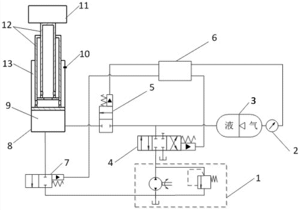
[0019] combine figure 1 :

[0020] A gas-liquid mixed multi-stage high-speed ejection device, including a hydraulic oil source 1, a control valve 4, a large flow switch valve 5, a common switch valve 7, an accumulator 3, a controller 6, a multi-stage ejection cylinder 8 and a load 11, The multi-stage ejection cylinder 8 is provided with a multi-stage sleeve type piston cylinder 12, the bottom of the multi-stage sleeve type piston cylinder 12 is in sliding and sealing cooperation with the multi-stage ejection cylinder 8, and the open end of the multi-stage ejection cylinder 8 is in contact with the multi-stage sleeve. The multi-stage ejection cylinder 8 is divided into a lower chamber 9 and an upper chamber 13 by the bottom of the multi-stage sleeve type piston cylinder 12. The upper chamber 13 is filled with oil, and the multi-stage sleeve type piston cylinder 12 is a two-layer sleeve structure, the inner sleeve is connected with the load, mainly the inner sleeve pushes the l...


PUM


Abstract

The invention discloses a gas-liquid mixed multistage high-speed catapult which comprises a hydraulic oil source, a control valve, a large-flow switching valve, a common switching valve, an energy accumulator, a controller, a multistage catapult cylinder and a load. The hydraulic oil source is connected with an oil inlet of the control valve. An oil outlet of the control valve is connected with a liquid part of the energy accumulator and an oil inlet of the large-flow switching valve. An oil outlet of the large-flow switching valve is connected with a lower cavity of the multistage catapult cylinder. The lower cavity of the multistage catapult cylinder is connected with an oil inlet of the common switching valve. A piston sleeve on the innermost layer of the multistage catapult cylinder is fixedly connected with the load. The control end of the control valve, the control end of the large-flow switching valve and the control end of the common switching valve are all connected with the controller. The oil outflow end of the common switching valve is connected with an oil tank of the hydraulic oil source. By the adoption of the gas-liquid mixed multistage high-speed catapult, the sealing difficulty in the high-speed catapulting process is effectively lowered through the multistage catapult cylinder and the controllability of the gas-liquid mixed multistage high-speed catapult is improved.

Description

technical field [0001] The invention belongs to the technical field of ejection devices, in particular to a gas-liquid mixed multistage high-speed ejection device. Background technique [0002] Existing ejection devices mainly include gun type, gas type, steam type, compressed air type, hydraulic type, hydraulic pneumatic type, electromagnetic type and the like. The cannon-type ejection mechanism has a high ejection speed, but the impact overload is large, and the ejection process is uncontrollable; the gas-fired ejection mechanism can efficiently convert chemical energy into kinetic energy of the ejection load, but there is high temperature ablation. The above two methods are rarely used. The widely used ejection methods are compressed air, steam, and hydraulic ejection, but steam ejection consumes a large amount of steam, the problem of gas sealing is always difficult to be effectively overcome, the energy utilization rate is extremely low, and the ejection acceleration d...

Claims


Application Information

Patent Timeline
Patent Type & Authority Patents(China)
IPC IPC(8): F15B11/072F15B1/02
CPCF15B1/02F15B11/072
Inventor 任锐马大为朱忠领
Owner NANJING UNIV OF SCI & TECH
Why Eureka
Try Eureka