Rotary blind rivet

A blind rivet and rotary technology, applied in the direction of rivets, etc., can solve the problems of increasing processing cost and assembly cost, axial force deviation, unstable installation, etc. The effect of loosening performance and reliability in use, saving processing costs and assembly costs

Active Publication Date: 2016-02-24
AEROSPACE PRECISION PROD INC LTD
View PDF6 Cites 2 Cited by
  • Summary
  • Abstract
  • Description
  • Claims
  • Application Information

AI Technical Summary

Problems solved by technology

[0003] The existing blind rivets are composed of three to five parts, and the structure is relatively complex. Due to the large number of parts, it is easy to produce axial force deviation during the installation process of the blind rivet, resulting in eccentric moments during the installation process. If it is too large, it will lead to unstable installation, uneven twist-off groove port, and even damage to parts.
The general rotary blind rivet has a lock ring, which is used to fix the nail sleeve after the blind rivet is broken, so as to prevent the fixing part from falling off. Looseness occurs. In addition, in order to ensure the locking effect of the lock ring, it is necessary to precisely process the specifications of the lock ring, which increases the processing cost and assembly cost

Method used


Image

  • Rotary blind rivet
  • Rotary blind rivet
  • Rotary blind rivet

Examples


Embodiment Construction

[0019] The present invention will be further described below with reference to the accompanying drawings.

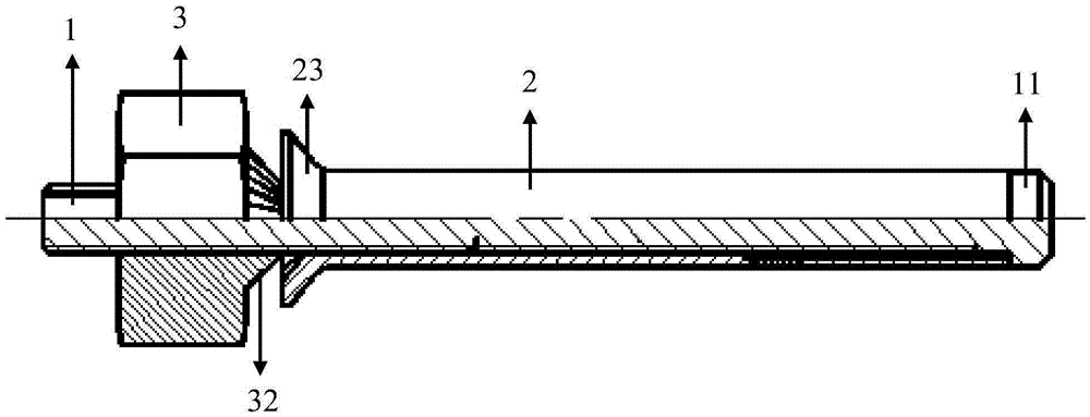
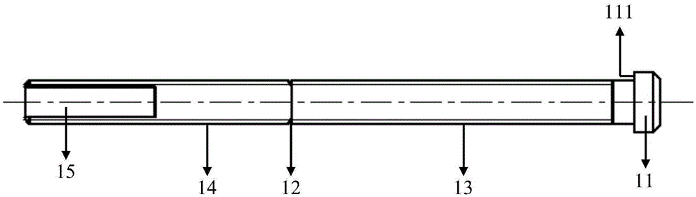
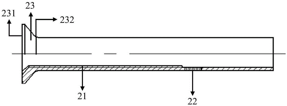
[0020] The present invention creates an embodiment of the structure such as Figure 1-4 As shown, it includes a core rod 1 and a sleeve body 2; one end of the core rod 1 is provided with a head protrusion 11, and the middle part is provided with a broken neck groove 12; A first thread segment 13 is provided from the side facing the head protrusion 11 and toward the head protrusion 11; From one side of the tail of the core rod, a second thread segment 14 is provided in the direction of the tail of the core rod; the sleeve body 2 can be sleeved on the core rod 1, and the sleeve body 2 has a The sleeve body thread segment 21 that the first thread segment 13 is engaged with; when one end of the sleeve body 2 is located on the inner end face 111 of the convex body 11 of the head of the core rod 1, the first thread segment 13 is partially or fully engaged with the threaded s...


PUM


Abstract

The invention provides a rotary blind rivet which comprises a core rod and a sleeve body. A head protruding body is arranged at one end of the core rod. A broken neck groove is formed in the middle of the core rod. A first thread section is arranged on the outer surface of the core rod from the broken neck groove to the head protruding body. A second thread section is arranged from the broken neck groove to the tail portion of the core rod. The core rod can be sleeved with the sleeve body. A sleeve body thread section which can be engaged with the first thread section is arranged in the sleeve body. The first thread section is partially or completely engaged with the sleeve body thread section. At least one annealing section is further arranged on the sleeve body. After the core rod is sleeved with the sleeve body, the annealing section is located between the broken neck groove and the head protruding body of the core rod. The thread of the first thread section is different from that of the second thread section. According to the rotary blind rivet, the structure integration degree is high, the number of parts is small, the installation reliability is high, and the requirements for safety of aerospace vehicles can be better met.

Description

technical field [0001] The invention belongs to the technical field of fastener design and manufacture, and in particular relates to a rotary blind rivet with a controllable neck-breaking groove. Background technique [0002] In aviation and aerospace vehicles, due to the strict control of their own weight, there are often cases where the installation space is small and workers cannot successfully install them. In this case, blind rivets, which can be used for single-sided riveting installation, are usually used for assembly. Considering the safety of aviation and aerospace vehicles, there are high requirements for the tensile, shear, preload, locking and other properties of blind rivets; at the same time, the flatness of the twisted groove port is also high. Require. [0003] The existing blind rivet is composed of three to five parts, and the structure is relatively complex. Due to the large number of parts, it is easy to cause the axial force to deviate during the insta...

Claims


Application Information

Patent Timeline
Patent Type & Authority Applications(China)
IPC IPC(8): F16B19/08
CPCF16B19/08
Inventor 刘智昂张晓斌郭双双桂林景魏亮亮单垄垄
Owner AEROSPACE PRECISION PROD INC LTD
Why Eureka
Try Eureka