Optimizing and designing system for dynamic property of fluidic-resistance suspension of automobile powertrain

A technology of automotive powertrain and hydraulic mount, which is applied to mechanical equipment, liquid shock absorbers, combustion engines, etc., can solve the problems of lack of theoretical basis for hydraulic mount, shorten the development cycle, reduce adjustments, Reduce the effect of work on structural improvements

Inactive Publication Date: 2016-02-24
BRILLIANCE AUTO
View PDF4 Cites 10 Cited by
  • Summary
  • Abstract
  • Description
  • Claims
  • Application Information

AI Technical Summary

Problems solved by technology

In order to solve the above unsatisfactory problems such as the lack of theoretical basis in the design and analysis of the liquid resistance mount, the design system can be used for the preliminary design and structural analysis of the liquid res

Method used


Image

  • Optimizing and designing system for dynamic property of fluidic-resistance suspension of automobile powertrain
  • Optimizing and designing system for dynamic property of fluidic-resistance suspension of automobile powertrain
  • Optimizing and designing system for dynamic property of fluidic-resistance suspension of automobile powertrain

Examples


Embodiment 1

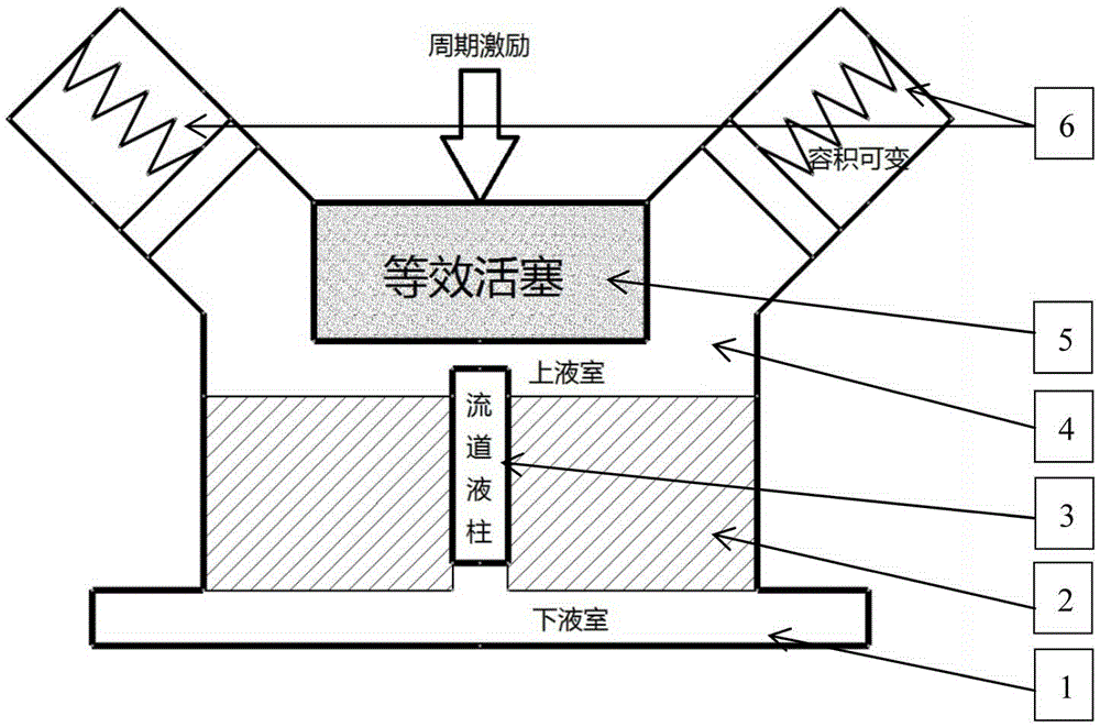
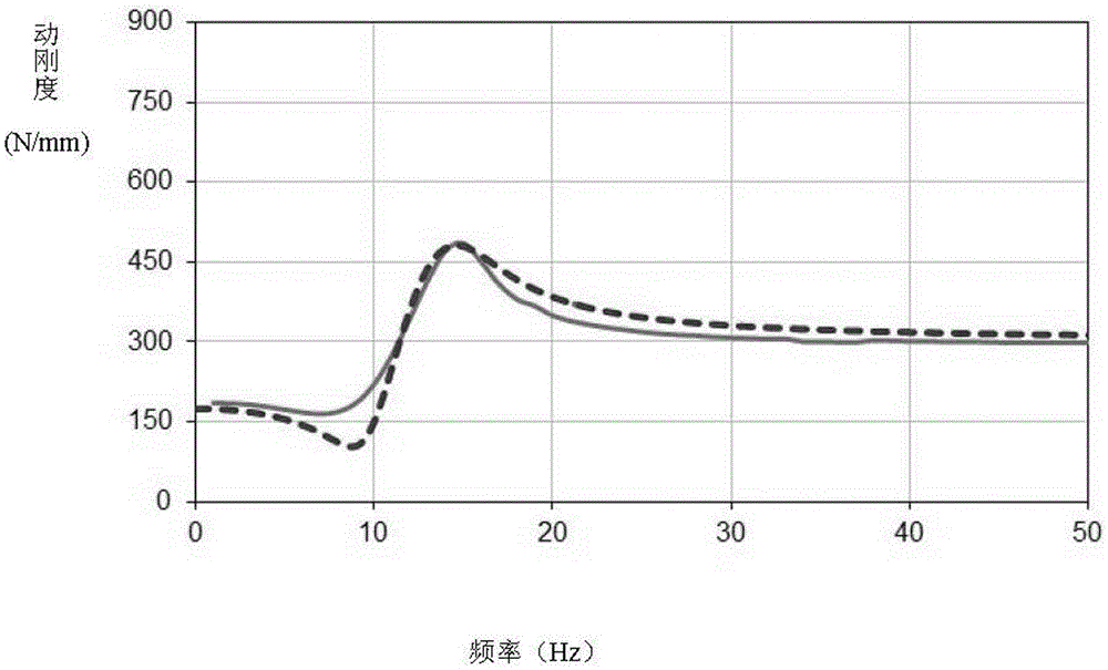
[0021] Depend on Figure 1-4 As shown in Fig. 1, the optimal design of the dynamic characteristics of a horizontal three-point engine side hydraulic mount. Finally, the optimally designed dynamic characteristic curve generated in the optimization design system and the dynamic test of the mount sample optimized by using the optimized design parameters are measured. line contrast.

Embodiment approach

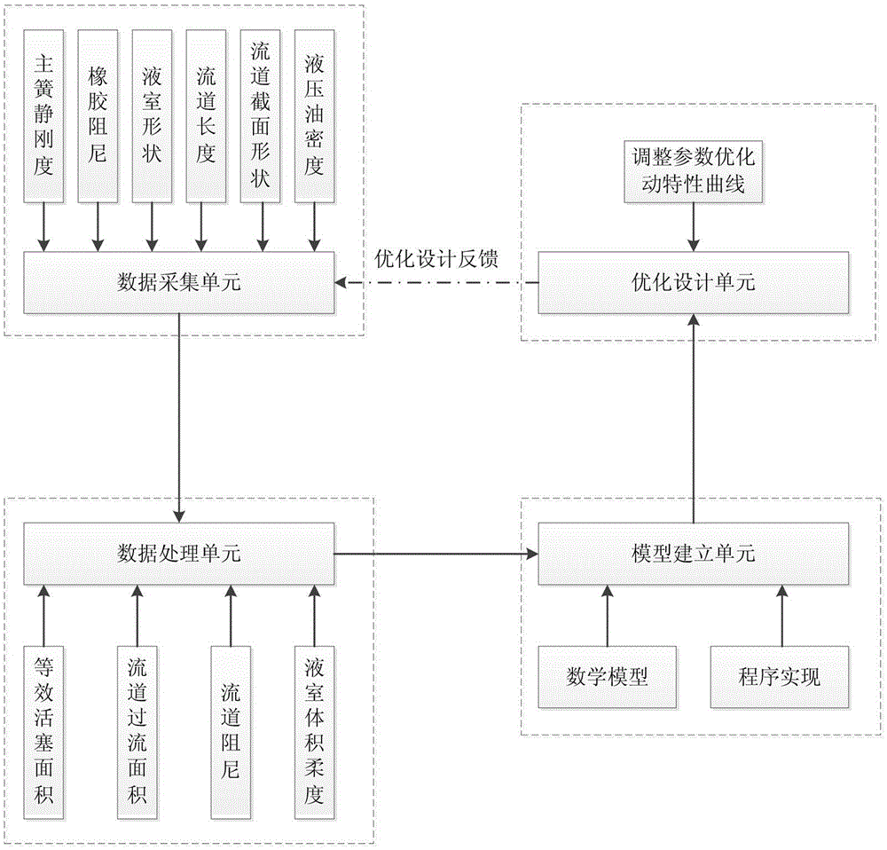
[0022] According to the optimization design system of the suspension dynamic characteristics of the present invention, according to figure 1 The specific implementation method of the system structure schematic diagram in is as follows:

[0023] It includes a data acquisition unit for determining or identifying the relevant parameters of the rubber main spring, the relevant parameters of the liquid chamber, the relevant parameters of the flow channel and the relevant parameters of the hydraulic oil. Connection; the output end of the data processing unit is connected with the input end of the model building unit, and the output end of the model building unit is connected with the input end of the optimization analysis unit;

[0024] The data processing unit refers to performing summary processing according to the collected parameters to obtain the key abstract parameters affecting the dynamic characteristics of the liquid resistance mount required for model building; the model e...


PUM


Abstract

The invention provides an optimizing and designing system for dynamic property of a fluidic-resistance suspension of an automobile powertrain. The optimizing and designing system is characterized in that firstly, the mechanical principle is utilized to determine relative structural parameters of the fluidic-resistance suspension, and the relative structure parameters include relative parameters of a rubber main spring, relative parameters of an upper liquid chamber and a lower liquid chamber, relative parameters of a runner and relative parameters of hydraulic oil; then, the actual working principle of the fluidic-resistance suspension is deep understood to construct a mechanical model of the fluidic-resistance suspension, and a functional structure can be abstracted into that the lower liquid chamber, a liquid chamber separating layer and the upper liquid chamber are sequentially arranged in a cavity from bottom to top; a runner liquid column is further arranged in the middle of the liquid chamber separating layer, and the runner liquid column can move along with harmonic excitation exerted at the top of the suspension; due to the fact of the changeable characteristic of the rubber liquid chamber, the upper liquid chamber above the runner liquid column can be simplified into an equivalent piston; and an elastic body of the upper liquid chamber can be simplified into the changeable volume with the rigidity to be shown through a left spring and a right spring. A correlation formula of representation property of the fluidic-resistance suspension is induced; the dynamic property, with the parameters optimized, of the fluidic-resistance suspension is achieved; and an optimized sample is obtained based on the dynamic property with the parameters optimized to obtain the optimal dynamic property.

Description

technical field [0001] The invention relates to the technical field of automobile mount systems, in particular to an optimal design system for dynamic characteristics of automobile powertrain fluid resistance mounts. Background technique [0002] With the continuous development of the automobile industry, people's requirements for driving comfort are also increasing, and the powertrain is the most important source of excitation for automobiles, and the quality of its vibration isolation is crucial to the vibration comfort of the vehicle. The core component of the modern automotive powertrain mount system, the dynamic performance of the fluid resistance mount directly determines the vibration attenuation of the mount system in the entire frequency range, especially at low frequencies. [0003] For a long time, for the structural design of liquid resistance mounts, all parties have tended to continue to use the mature structures of previous models, especially the key structure...

Claims


Application Information

Patent Timeline
IPC IPC(8): F16F9/22
CPCY02T10/40
Inventor 苗为为刘艳华刘通任爽王紫璇陈奇苗贺
Owner BRILLIANCE AUTO
Why Eureka
Try Eureka