Light collecting device and headlamp provided with light splitting structure

A light collection and headlamp technology, applied in the field of lighting, can solve the problems of unreliability and high manufacturing cost of headlamps, and achieve the effects of improving reliability, simple structure and uniform structure

Active Publication Date: 2016-02-24
CHENGDU HERCULUX OPTOELECTRONICS TECH CO LTD
View PDF5 Cites 3 Cited by
  • Summary
  • Abstract
  • Description
  • Claims
  • Application Information

AI Technical Summary

Problems solved by technology

[0008] The object of the present invention is to provide a headlight that can reduce the production cost and has good reliability in view of the current problems of high manufacturing cost and unreliability of the headlight.

Method used


Image

  • Light collecting device and headlamp provided with light splitting structure
  • Light collecting device and headlamp provided with light splitting structure
  • Light collecting device and headlamp provided with light splitting structure

Examples


Embodiment 2

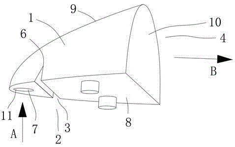
[0048] Example 2, such as figure 1 with 5 as shown,

[0049] As in the light collecting device described in Embodiment 1, a notch 3 is provided on the lens body, and the wall surface of the notch 3 serves as the light splitting structure 2 .

[0050] In the above scheme of the present application, the light collecting device is set as a lens body, the lens body is provided with a notch 3, and the wall surface of the notch 3 is used as the light splitting structure 2, that is to say, the light collecting device of the present application passes through the lens body. The wall is used as the light splitting structure 2, and part of the light emitted to the headlight projection device 12 is refracted or reflected by the wall surface of the lens body, so that the headlight projection device 12 projects a light distribution pattern that meets the requirements. Structure 2 has a better integration, which directly avoids the risk of relative position changes, further improves the r...

Embodiment 3

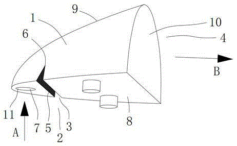
[0051] Example 3, such as image 3 with 5 or 4 and 5,

[0052] As in the light collecting device described in Embodiment 1, the lens body has an exit end 4, and the light emitted by the headlight light source 13 is collected by the light collecting device body 1 and emitted from the exit end 4, and then shot forward. In the lamp projection device 12 , part of the end surface of the emitting end 4 is the light splitting structure 2 .

[0053] In the above solution of the present application, part of the end surface of the exit end 4 of the lens body is used as the light splitting structure 2, which further facilitates the processing and manufacturing of the light collection device of the present application, and reduces the difficulty and cost of processing and manufacturing the light collection device.

Embodiment 4

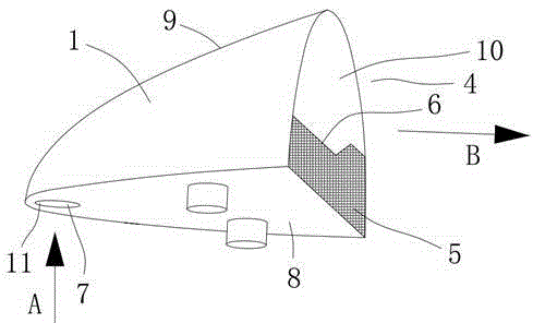
[0054] Example 4, such as Figure 1-5 as shown,

[0055] In the light collection device according to any one of embodiments 1-3, the light splitting structure 2 reflects the light irradiated thereon back into the light collection device body 1, and the light reflected by the light splitting structure 2 passes through the The light collecting device body 1 collects it again and emits it to the headlight projecting device 12 .

[0056] In the above solution of the present application, the light reflected by the light splitting structure 2 is collected and utilized by the light collecting device body 1 again, which improves the utilization rate of the headlight light source 13, and then makes it possible to use the light source of the present application under the premise of obtaining the same light intensity. The advanced light collection device can reduce the power of the light source 13, while reducing the cost, it also reduces the calorific value of the light source 13, impr...


PUM


Abstract

The invention relates to the technical field of illumination and particularly relates to a light collecting device and a headlamp provided with a light splitting structure. The light collecting device comprises a light collecting device body which is provided with the light splitting structure; the light splitting structure is used for reflecting or refracting some light emitted by the light collecting device body to a projecting device of the headlamp, so that the projecting device can be used for projecting a pattern which satisfies illumination and light distribution of the headlamp. According to the light collecting device disclosed by the invention, from the viewpoint of energy saving, the separated light can be utilized by subsequent transformation, so the utilization rate of light energy is increased. From the viewpoint of structure, the possibility of relative displacement between the light collecting device body and the light splitting structure is directly avoided, so the position of the light collecting device body and the position of the light splitting structure are fixed no matter during transportation or after the light collecting device is mounted on a vehicle; therefore, the reliability of the headlamp is improved; during manufacturing, the procedures of an assembly process are reduced, and the assembly difficulty is reduced.

Description

technical field [0001] The invention relates to the technical field of lighting, in particular to a light collecting device and a headlamp with a light splitting structure. Background technique [0002] In the field of automotive lighting technology, the state has announced GB7454-87 "Technical Planning for the Use and Light Adjustment of Motor Vehicle Headlamps", GB4599-2007 "Light Distribution Performance of Headlamps" and GB4660-2007 "Fog Lamps with Filament Bulbs for Automobiles" 》Present clear requirements on the luminous intensity and irradiation direction of high beam lighting, low beam lighting and fog lamps of motor vehicles. [0003] For the low beam of the headlights, it is required that the emitted light must form a clear cut-off line. For the formation of the cut-off line, the technology of shading is mainly used at present. The principle is that the light source emits Part of the light is blocked by setting a shading plate to form a light and dark area, and a ...

Claims


Application Information

Patent Timeline
IPC IPC(8): F21S8/10F21V5/04F21W101/02F21W101/10F21W107/10
CPCF21S41/00F21S41/27F21W2102/00F21W2107/10
Inventor 霍永峰
Owner CHENGDU HERCULUX OPTOELECTRONICS TECH CO LTD
Why Eureka
Try Eureka